
Interdental cleaning device

Inactive Publication Date: 2017-11-09
SUNSTAR INC
View PDF3 Cites 11 Cited by
  • Summary
  • Abstract
  • Description
  • Claims
  • Application Information

AI Technical Summary

Benefits of technology

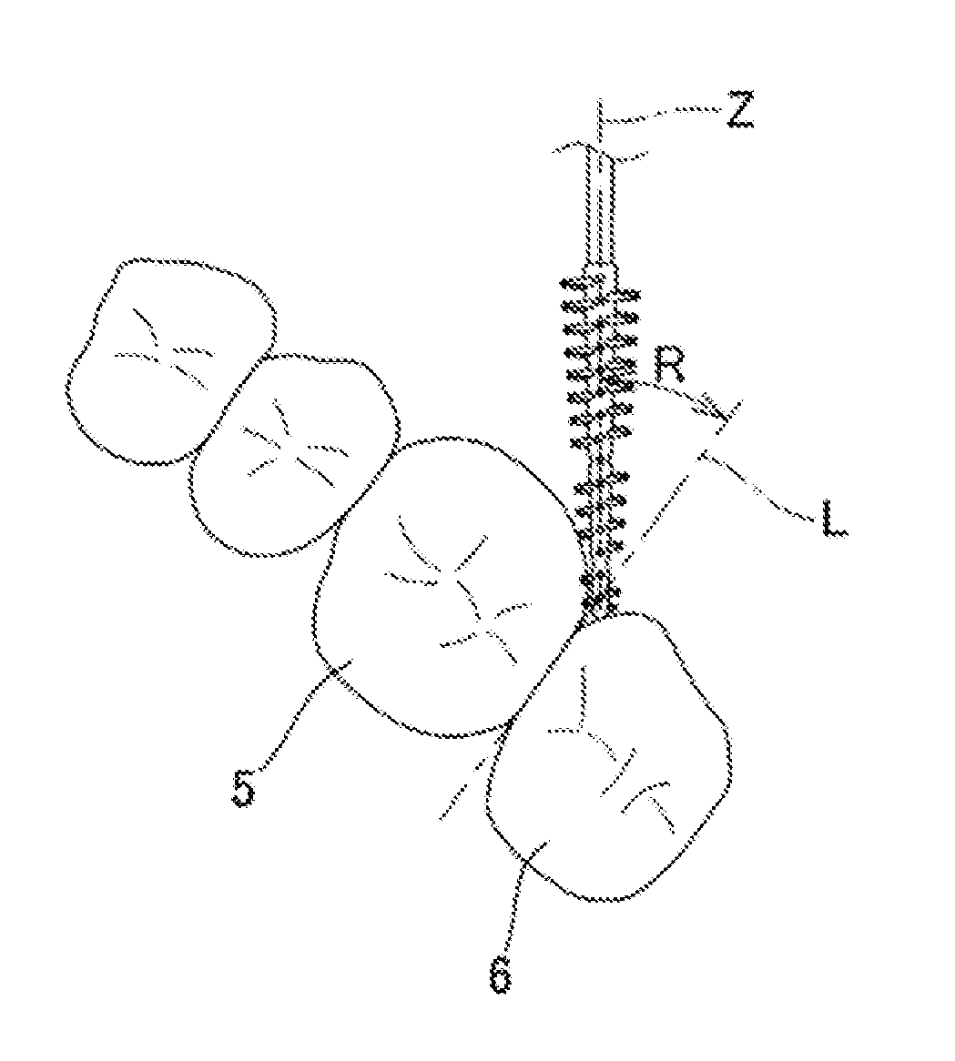
The interdental cleaning device described in this patent can help prevent it from breaking during insertion between molar teeth.

Problems solved by technology

However, the metal wires tend to easily hurt the teeth and gum when inserted into interdental spaces.

Method used


Image

  • Interdental cleaning device
  • Interdental cleaning device
  • Interdental cleaning device

Examples


Embodiment Construction

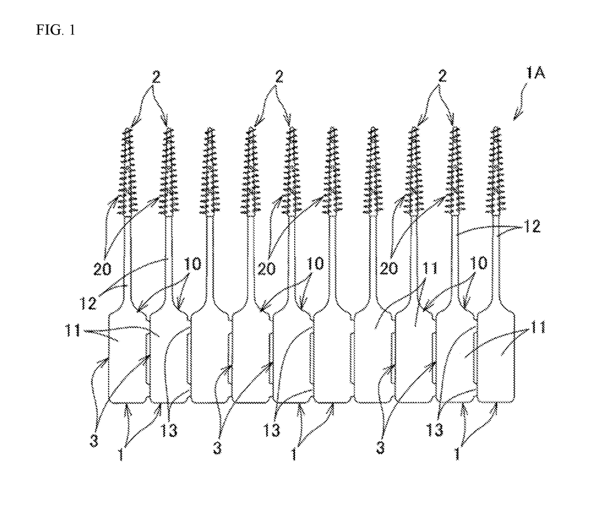
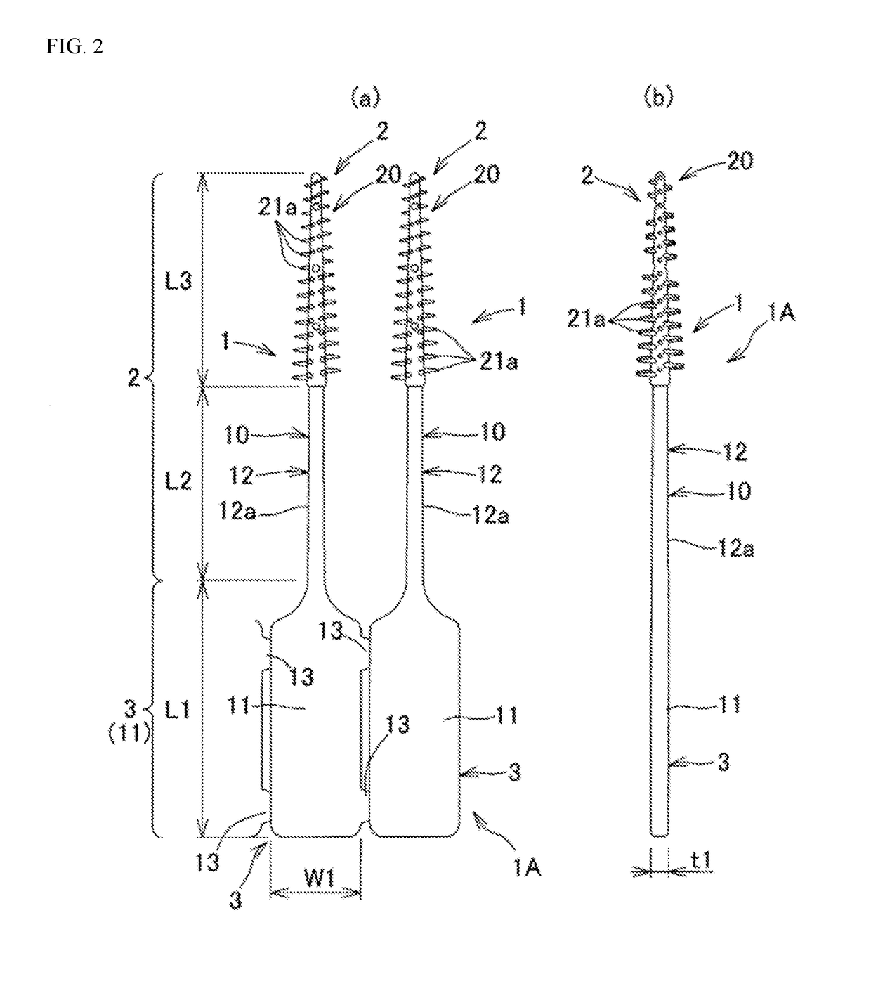
[0045]Hereinafter, embodiments of the present invention will be described with reference to the drawings. Note that in the respective drawings, the same elements are denoted by the same reference signs, and a repeated description thereof will be omitted. FIG. 1 is a front view of an interdental cleaning device chain 1A having a plurality of interdental cleaning devices 1 according to an embodiment of the present invention connected to one another. The interdental cleaning device chain 1A illustrated in FIG. 1 includes a plurality of interdental cleaning devices 1 connected integrally to one another. FIGS. 2(a) and 2(b) are partially enlarged views of the interdental cleaning device chain 1A illustrated in FIG. 1. FIG. 2(a) illustrates the front view, and FIG. 2(b) illustrates the side view.

[0046]The interdental cleaning device 1 illustrated in FIGS. 2(a) and 2(b) includes a cleaning portion 2 for interdental cleaning and a handle portion 3 connected as a grip to the cleaning portion...


PUM

PropertyMeasurementUnit
Lengthaaaaaaaaaa
Lengthaaaaaaaaaa
Lengthaaaaaaaaaa

Abstract

An interdental cleaning device (1) for being inserted into an interdental space to clean the interdental space includes a rod-shaped core portion (12); and a soft portion (20) being softer than the core portion (12) and covering the outer surface of at least a part of the core portion (12) including a core front end (P1) as the front end of the core portion (12), wherein the soft portion (20) has a partial length of 0.5 mm or more between the core front end (P1) and a soft front end (P2) as the front end of the soft portion (20).

Description

TECHNICAL FIELD[0001]The present invention relates to an interdental cleaning device for cleaning interdental spaces.BACKGROUND ART[0002]An interdental cleaning device (interdental brush) used widely includes a core portion composed of twisted two thin metal wires; and a brush portion having filaments fixed between the two thin wires. However, the metal wires tend to easily hurt the teeth and gum when inserted into interdental spaces. Thus, various other interdental cleaning devices are proposed and commercialized, which have a synthetic resin core portion; a cleaning soft portion that is made of an elastomer and molded to cover a front end portion of the core portion; and a gripping portion provided at the rear end of the core portion, in which the core portion and the cleaning soft portion form a cleaning portion to be inserted between teeth (see, for example, Patent Literature 1).CITATIONS LISTPatent Literature[0003]Patent Literature 1: Japanese Unexamined Patent Application Publ...

Claims


Application Information

Patent Timeline
IPC IPC(8): A61C15/02A46B9/02A46B5/00A46B9/04A46B15/00
CPCA61C15/02A46B9/026A46B2200/108A46B5/0029A46B15/0093A46B9/04
Inventor GENGYO, ANRIKATO, KEISUKE
Owner SUNSTAR INC
Learn More