
An apparatus for guiding a surgical needle

a technology for guiding surgical needles and needles, applied in the direction of magnetic variable regulation, instruments, applications, etc., can solve the problems of increasing radiation exposure to patients with ct scanning, changing the actual angle of entry after attachment, and relatively inconvenient operation, so as to improve the accuracy of surgical needle entry

Active Publication Date: 2017-11-02
CHIENG YEN YUNG
View PDF13 Cites 12 Cited by
  • Summary
  • Abstract
  • Description
  • Claims
  • Application Information

AI Technical Summary

Benefits of technology

The patent is about a device used to position a needle in a patient for procedures like brain surgeries. The device has a needle guide that can be released from a support to allow for precise positioning. The device also has a base that can be aligned with a scan plane using a laser line produced by a scanning apparatus. This makes it easier to position the device on the patient. Overall, the device helps improve the accuracy of procedures and minimize the risk to the patient.

Problems solved by technology

The disadvantage of this procedure is the protracted operation time with multiple needle entries which can lead to discomfort and increased radiation exposure to the patient with CT scanning.
The disadvantage with these known devices is that they are still relatively imprecise in matching the exact angle of entry of the surgical needle in axial and cranio-caudal planes to that calculated by an imaging machine, in that the apparatus has to be configured with the predicted angle of entry before attaching to the body of a patient, which may result in a change in the actual angle of entry after attachment if the patients body surface is not flat.
In this way, known devices still frequently require repeated needle entry and scans to achieve a successful biopsy.
However these apparatus are bulky, costly to maintain with expensive software upgrades and difficult to operate, requiring highly specialist surgical skills.

Method used


Image

  • An apparatus for guiding a surgical needle
  • An apparatus for guiding a surgical needle
  • An apparatus for guiding a surgical needle

Examples


Embodiment Construction

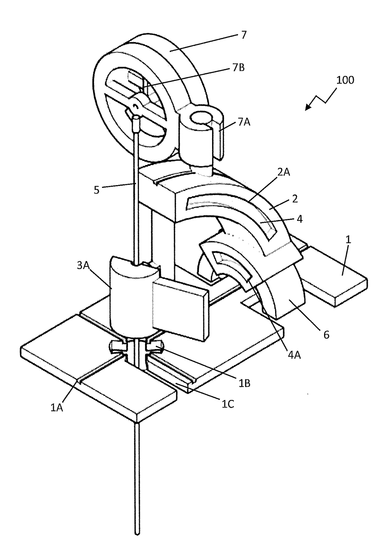
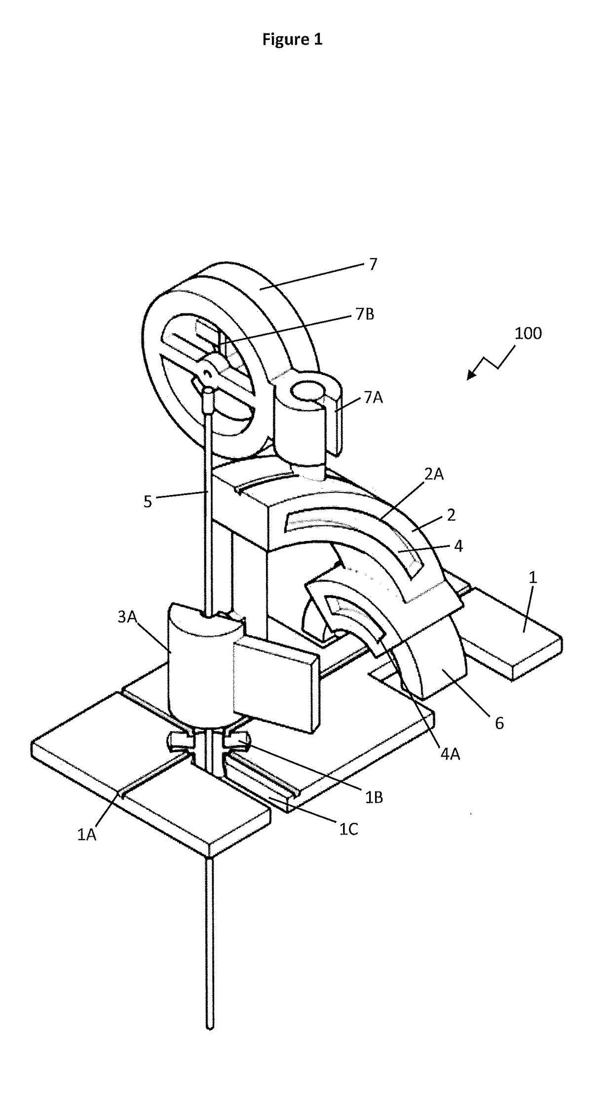
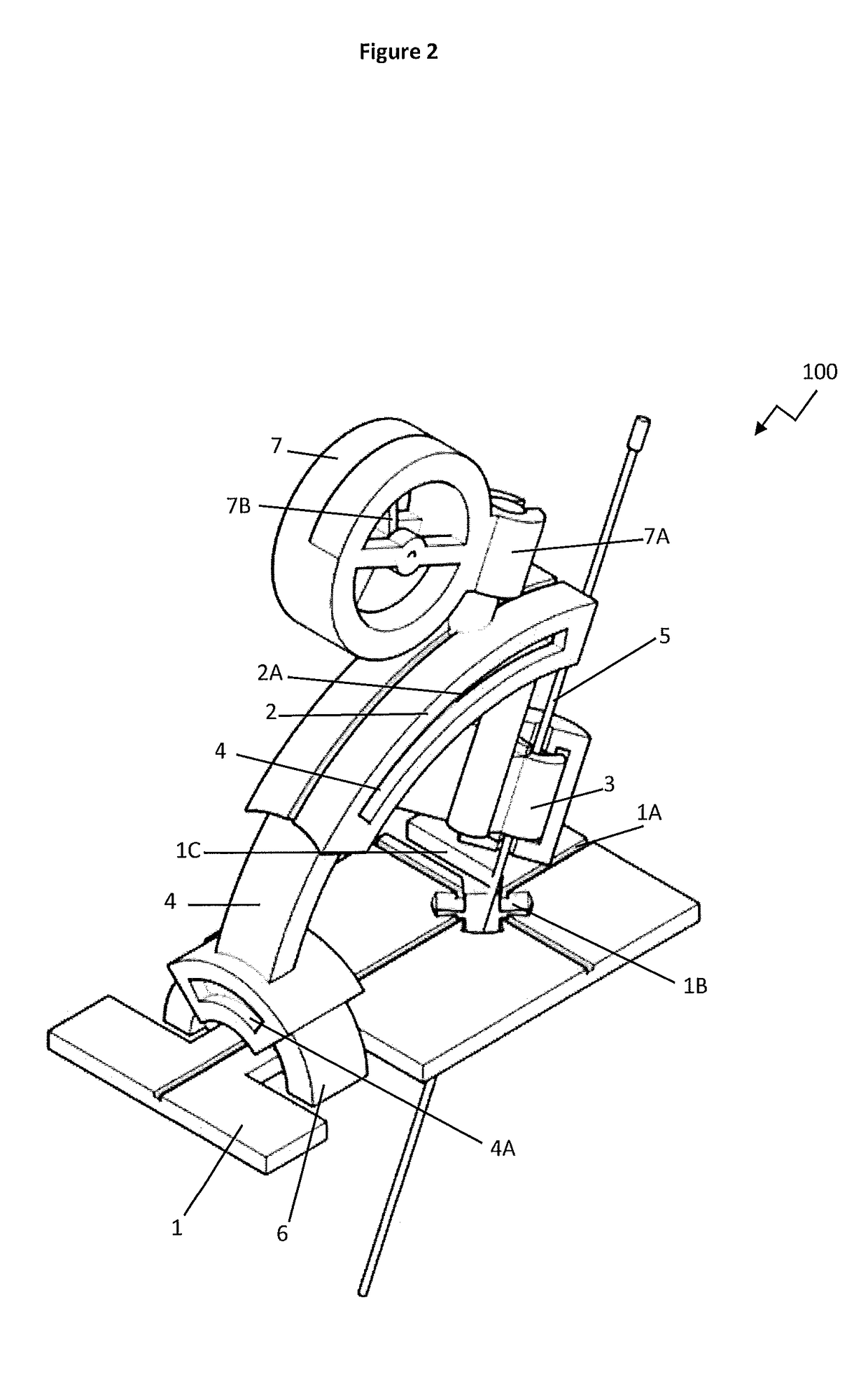
[0060]Referring to FIGS. 1 to 9, in a preferred form of the present invention, an apparatus for guiding a surgical needle is generally indicated by arrow 100. The apparatus (100) comprises a base (1) configured for placement of the apparatus (100) on a patients skin. While the apparatus (100) is envisaged for use on a torso of a patient this should not be seen to limited the scope of the invention as the apparatus (100) could be used on other areas of a patents body to perform biopsy of a lesion.

[0061]The apparatus (100) also comprises an arm (2) attached at one end to a needle guide support in the form of a C-shaped clamp (3) and attached at its distal end to a first arc member (4). The C-shaped clamp (3) facilitates attachment of a surgical needle guide (5) for a surgical needle (not shown). The C-shaped clamp (3) has a sliding carriage (3A) configured to accommodate needle guides of different diameters and to facilitate rotation of the needle guide (5) within the C-shaped clamp (...


PUM


Abstract

An apparatus (100) for guiding a surgical needle with improved accuracy. The apparatus (100) having a base (1) for positioning the apparatus (100) on a patient; a second arc member (6) attached to the base (1); a first arc member (4) moveably attached to the second arc member (6); an arm (2) attached to a needle guide support (3) at one end and moveably attached to the first arc member (4) at a distal end, and an angle marking device (7) attached to the arm (2) to indicate a vertical reference point for measuring the angle of tilt of the arm (2) from the vertical reference point relative to the base (1). Wherein the first arc member (4) is configured to move on the second arc member (6) to facilitate movement of the needle guide support (3) in a cranio-caudal plane and the arm (2) is configured to move on the first arc member (4) to facilitate movement of the needle guide support (3) in an axial plane.

Description

STATEMENT OF CORRESPONDING APPLICATIONS[0001]This application is based on the Provisional specification filed in relation to New Zealand Patent Application Number 701196, the entire contents of which are incorporated herein by reference.TECHNICAL FIELD[0002]The present invention relates generally to an apparatus for guiding a surgical needle. In particular, the present invention relates to an apparatus for guiding a surgical needle for use in determining the position of entry of a surgical needle in the torso of a human patient during surgery.BACKGROUND ART[0003]Typically the point and angle of entry of a surgical needle (such as a biopsy needle) in a patient is first calculated by scanning the patient via an imaging technique such as computed tomography (CT) or magnetic resonance imaging (MRI) with imaging surface markers placed on the patient (such as the torso). The point of needle entry is typically selected with reference the most appropriate imaged position marker and the angl...

Claims


Application Information

Patent Timeline
Patent Type & Authority Applications(United States)
IPC IPC(8): A61B17/34A61B10/02A61B34/30A61B90/00G01R33/28
CPCA61B17/3403A61B10/0233G01R33/285A61B2090/067A61B34/30A61B2017/3407A61B2090/069A61B90/11A61B90/13
Inventor CHIENG, YEN YUNG
Owner CHIENG YEN YUNG
Learn More