
Communication system

Active Publication Date: 2017-10-12
NEC CORP
View PDF6 Cites 17 Cited by
  • Summary
  • Abstract
  • Description
  • Claims
  • Application Information

AI Technical Summary

Benefits of technology

The patent describes a version of standards for machines that use a reduced bandwidth of 1.4 MHz for both uplink and downlink. This allows these machines to be made more economically compared to machines that support a larger bandwidth. The reduced bandwidth MTC devices may have fewer or simpler components than large bandwidth MTC devices.

Problems solved by technology

MTC devices might also remain stationary and / or inactive for a long period of time.

Method used


Image

  • Communication system
  • Communication system
  • Communication system

Examples


Embodiment Construction

[0035]

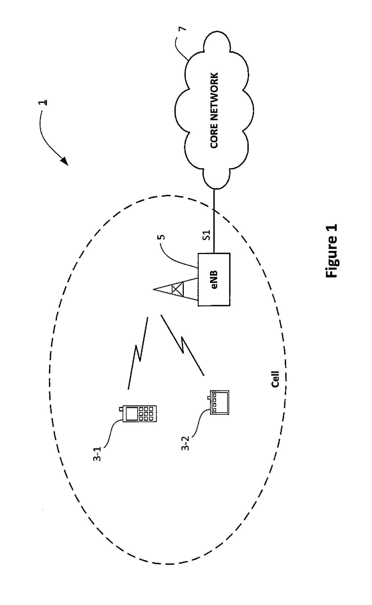
[0036]FIG. 1 schematically illustrates a mobile (cellular) telecommunication system 1 in which communication devices 3 (such as mobile telephone 3-1 and MTC device 3-2) can communicate with each other and / or with other communication nodes via an E-UTRAN base station 5 (denoted ‘eNB’) and a core network 7. As those skilled in the art will appreciate, whilst one mobile telephone 3-1 one MTC device 3-2 and one base station 5 are shown in FIG. 1 for illustration purposes, the system, when implemented, will typically include other base stations and communication devices.

[0037]The base station 5 is connected to the core network 7 via an S1 interface. The core network 7 includes, amongst others: a gateway for connecting to other networks, such as the Internet and / or to servers hosted outside the core network 7 a mobility management entity (MME) for keeping track of the locations of the communication devices 3 (e.g. the mobile telephone and the MTC device) within the communication net...


PUM


Abstract

A communication system is described in which machine-type communication devices having a reduced bandwidth can be allocated physical uplink control channel resources that fall within that reduced bandwidth whilst other, legacy, devices can continue to use physical uplink control channel resources that do not fall within that reduced bandwidth.

Description

TECHNICAL FIELD[0001]The present invention relates to mobile communications devices and networks, particularly but not exclusively those operating according to the 3rd Generation Partnership Project (3GPP) standards or equivalents or derivatives thereof. The invention has particular although not exclusive relevance to the Long Term Evolution (LTE) of UTRAN (called Evolved Universal Terrestrial Radio Access Network (E-UTRAN)), including LTE-Advanced.BACKGROUND ART[0002]In a mobile (cellular) communications network, (user) communication devices (also known as user equipment (UE), for example mobile telephones) communicate with remote servers or with other communication devices via base stations. In their communication with each other, communication devices and base stations use licensed radio frequencies, which are typically divided into frequency bands and / or time blocks.[0003]In order to be able to communicate via the base stations, communication devices need to monitor control chan...

Claims


Application Information

Patent Timeline
IPC IPC(8): H04W72/04H04W4/00H04W4/70
CPCH04W72/048H04W4/005H04W72/0446H04W72/0413H04W4/70H04W72/51H04W16/14H04W72/04H04W72/0453H04W72/21
Inventor AWAD, YASSIN ADENCHEN, YUHUASHARMA, VIVEK
Owner NEC CORP
Learn More