
Motor control device and steering control device

a technology of steering control device and control device, which is applied in the direction of electric devices, electric commutators, electric devices, etc., can solve the problems of lowering the reliability of the motor control device and the reliability of the steering control device, and achieve the effect of suppressing the reduction of reliability

Inactive Publication Date: 2017-09-21
JTEKT CORP
View PDF2 Cites 18 Cited by
  • Summary
  • Abstract
  • Description
  • Claims
  • Application Information

AI Technical Summary

Benefits of technology

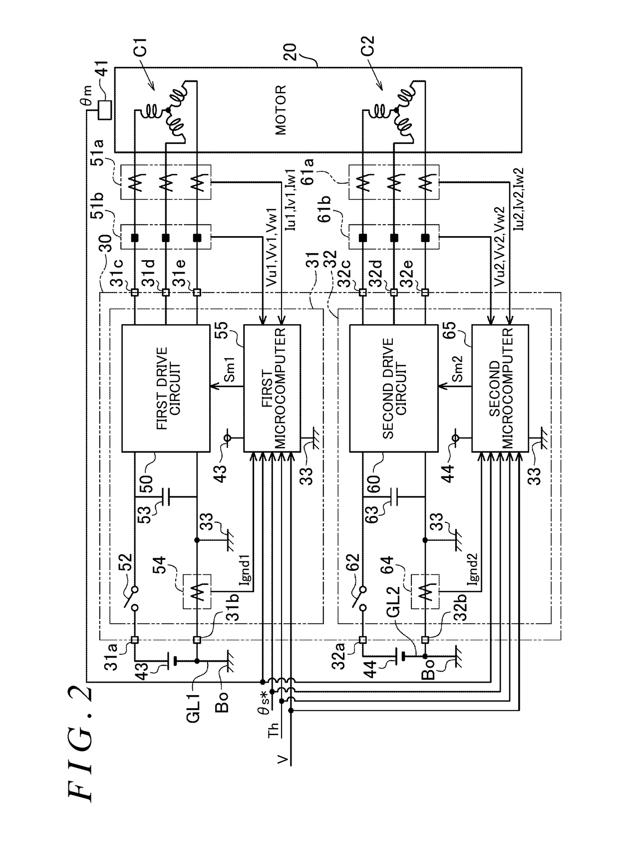
The present invention aims to provide a motor control device and a steering control device that can prevent a reduction in reliability even if the redundancy of the electric power source of drive electric power is increased. The invention has multiple current detection circuits placed between the power source grounds and the internal ground, which can detect the characteristic state of ground currents in case of an abnormality like a short circuit. This allows for the detection of abnormalities of power source grounds and ensures that the control system can address them quickly, preventing any reduction in reliability of the motor control device. Thus, the invention can provide a solution to increase reliability of the motor control device in such situations.

Problems solved by technology

Therefore, in the case where the redundancy of the electric power source of drive electric power is increased, it is difficult to detect an abnormality in the power source grounds even if operation of the motor control device is monitored from the outside, which may lower the reliability of the motor control device.
To increase the redundancy of the electric power source of drive electric power as in the example described above in such a steering control device, an abnormality in the power source ground may not be detected immediately, e.g. the timing to stop the automated drive function may be delayed, which may lower the reliability of the steering control device.

Method used


Image

  • Motor control device and steering control device
  • Motor control device and steering control device
  • Motor control device and steering control device

Examples


first embodiment

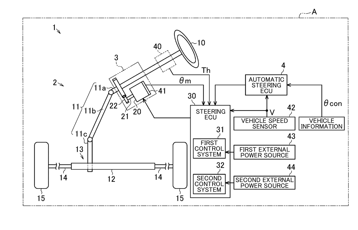
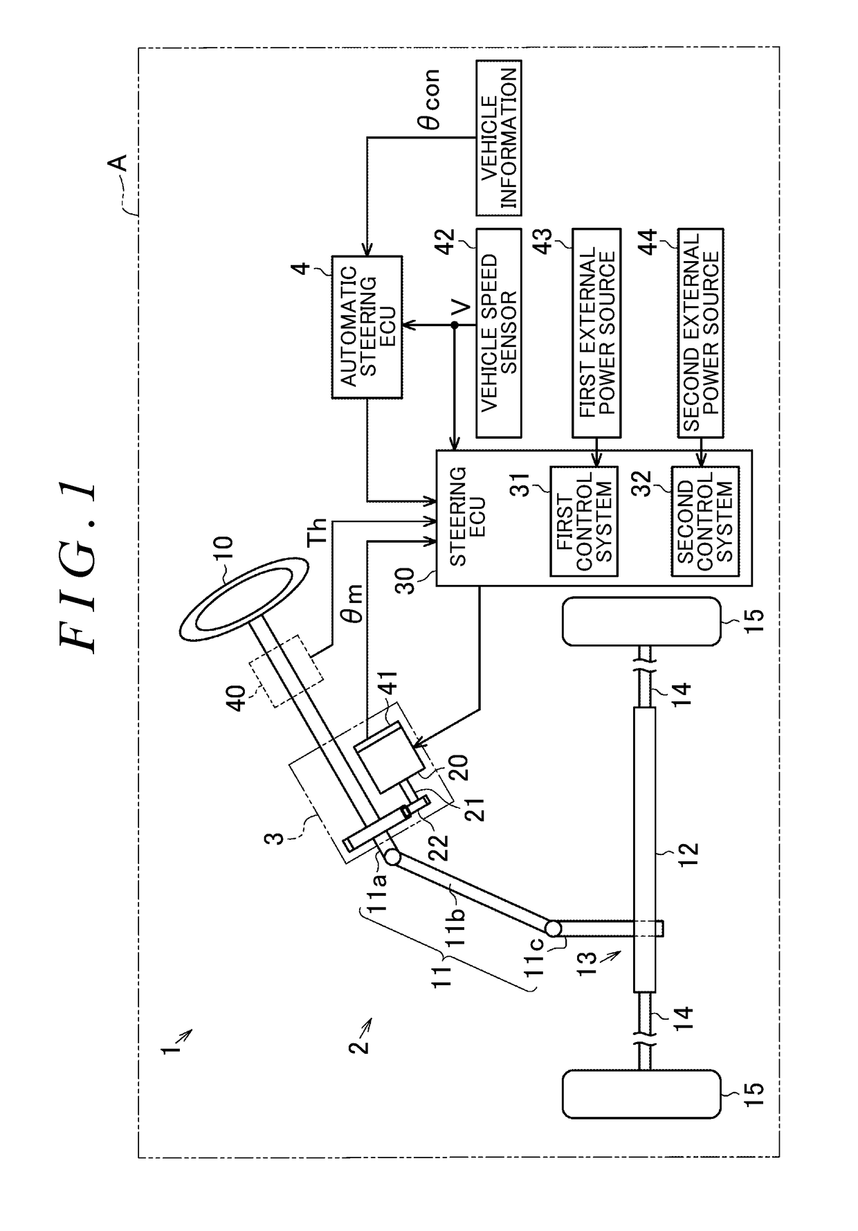
[0023]A motor control device and a steering control device will be described below. As illustrated in FIG. 1, a vehicle A is provided with an automatic steering device 1 configured to provide a steering mechanism 2 to be discussed later with power for automatically varying the travel direction of the vehicle.

[0024]The steering mechanism 2 includes a steering wheel 10 operated by a user, and a steering shaft 11 fixed to the steering wheel 10. The steering shaft 11 has a column shaft 11a coupled to the steering wheel 10, an intermediate shaft 11b coupled to the lower end portion of the column shaft 11a, and a pinion shaft 11c coupled to the lower end portion of the intermediate shaft 11b. The lower end portion of the pinion shaft 11c is coupled to a rack shaft 12 via a rack-and-pinion mechanism 13. Rotational motion of the steering shaft 11 is converted into reciprocal linear motion of the rack shaft 12 in the axial direction via the rack-and-pinion mechanism 13. The reciprocal linea...

second embodiment

[0087]Next, a motor control device and a steering control device will be described below. Components etc. that are the same as those of the embodiment described already are given the same reference numerals to omit redundant description.

[0088]As illustrated in FIG. 5, the steering ECU 30 according to the embodiment includes a first control system 31 that supplies drive electric power to a first system coil C1 of the motor 20, a second control system 32 that supplies drive electric power to a second system coil C2 of the motor 20, and an integral microcomputer 80 that integrally controls the control systems 31 and 32 in place of microcomputers 55 and 65. The voltage sensors 51b and 61b are not required for the steering ECU 30 according to the embodiment.

[0089]The integral microcomputer 80 controls operation of the drive circuits 50 and 60 and the power source relays 52 and 62 in the control systems 31 and 32. The integral microcomputer 80 receives, as inputs, various information (el...


PUM


Abstract

A steering control device capable of suppressing a reduction in reliability even in the case where the redundancy of the power source is increased is provided. A steering ECU includes two control systems in which different external power sources are connected to two drive circuits. The low potential sides of the drive circuits and the low potential sides of the corresponding external power sources are independently connected to each other via power source ground lines for the two control systems. The low potential sides of the drive circuits are connected to each other via an internal ground. Two current detection circuits are provided between the power source ground lines and the internal ground to detect power source ground current values, respectively. The steering ECU includes microcomputers that detect a ground abnormality on the basis of the results of detection performed by the current detection circuits.

Description

INCORPORATION BY REFERENCE[0001]The disclosure of Japanese Patent Application No. 2016-054175 filed on Mar. 17, 2016 including the specification, drawings and abstract, is incorporated herein by reference in its entirety.BACKGROUND OF THE INVENTION[0002]1. Field of the Invention[0003]The present invention relates to a motor control device and a steering control device.[0004]2. Description of the Related Art[0005]Japanese Patent Application Publication No. 2015-80327 (JP 2015-80327 A), for example, discloses a motor control device that includes two control systems (control units or inverters) that supply drive electric power to a motor using external power sources as electric power sources. The motor control device also includes two electric power supply paths that connect between the two control systems and the external power sources, respectively. This increases the redundancy of the control system in the motor control device described in JP 2015-80327 A.[0006]To increase the redun...

Claims


Application Information

Patent Timeline
Patent Type & Authority Applications(United States)
IPC IPC(8): H02P6/12H02P25/22B62D5/04H02P6/16
CPCH02P6/12H02P6/16B62D5/0484B62D5/0487H02P25/22B62D5/0481H02P27/00B60L3/0069B60L3/04B60L3/12B62D5/046B62D15/025B60L50/62H02P6/28Y02T10/62Y02T10/64Y02T10/70B60L3/0046H02P27/08H02P31/00Y02T10/7072
Inventor KAWAMURA, HIROSHITAKAHASHI, TOSHIHIRONIWA, TOMOHIROTOYOZUMI, KENICHIHASHIMOTO, TAKAHITO
Owner JTEKT CORP
Learn More