
Organic electroluminescent element, display device, lighting device, pi-conjugated compound, and light-emitting thin film

Active Publication Date: 2017-09-21
MERCK PATENT GMBH
View PDF6 Cites 9 Cited by
  • Summary
  • Abstract
  • Description
  • Claims
  • Application Information

AI Technical Summary

Benefits of technology

The present invention provides an organic electroluminescent element that can achieve restrained broadening of absorption and emission spectra and high efficiency without using rare metals. This element can be used in display devices and lighting devices. A π-conjugated compound is used to achieve this restraining effect. The compound has a specific angle with its electron donor and acceptor portions that allows for high efficiency. The angle of the compound is important for achieving this effect. By using this compound, the organic electroluminescent element can achieve high efficiency and reduced broadening of its spectra.

Problems solved by technology

This may induce an industrial problem of the amount of deposits or the cost of the rare metals in the future.
Although this technique can increase power efficiency of a fluorescence emission material (hereafter, it is called as a fluorescent emission material or fluorescent material) from two to three times larger than the power efficiency of a conventional fluorescent material, the emission efficiency in TTA is not as high as that of the aforementioned phosphorescent material due to a theoretical limitation, because the rate of conversion of the excited triplet energy level to the excited singlet energy level will remain to about 40%.
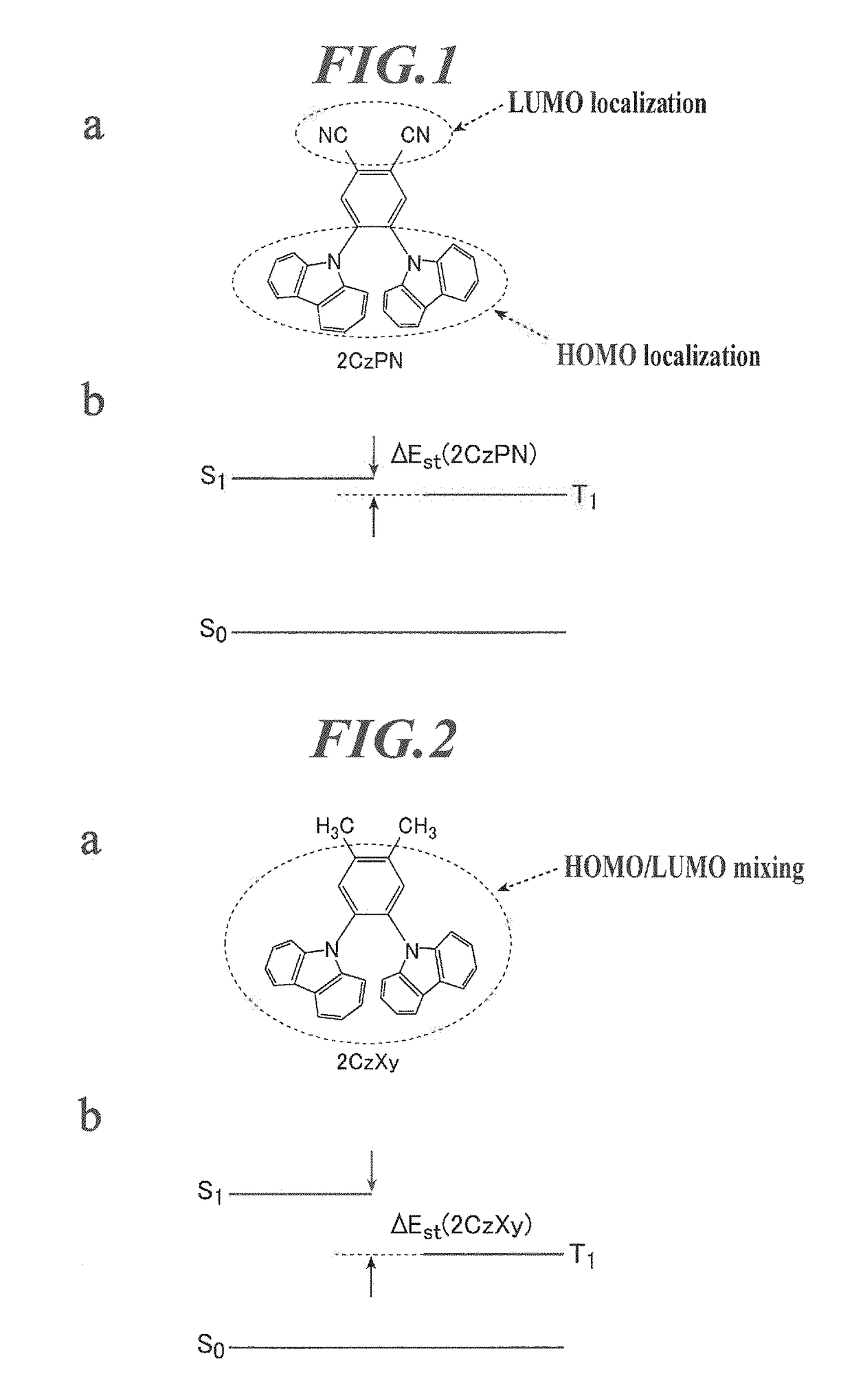
As a result, ΔEST cannot be made small, and a TADF phenomenon will not be produced.
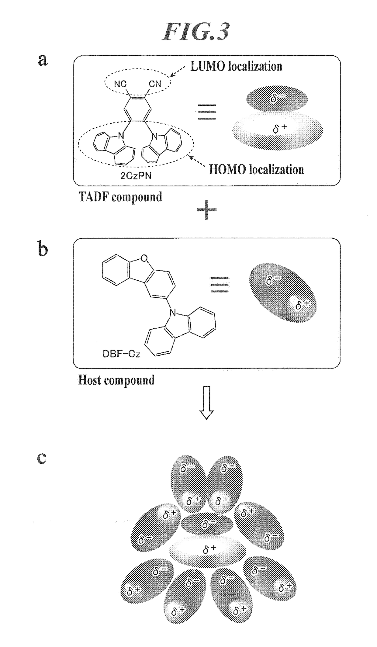
This broadening phenomenon becomes a fatal problem for a color designing of an organic EL element.
This charge imbalance will induce imbalance in the medium substance (for example, a solvent or a host compound, see “b” of FIG. 3).

Method used


Image

  • Organic electroluminescent element, display device, lighting device, pi-conjugated compound, and light-emitting thin film
  • Organic electroluminescent element, display device, lighting device, pi-conjugated compound, and light-emitting thin film
  • Organic electroluminescent element, display device, lighting device, pi-conjugated compound, and light-emitting thin film

Examples


example 1

(Preparation of Organic EL Element 1-1)

[0358]An anode was prepared on a glass substrate of 50 mm×50 mm with a thickness of 0.7 mm by forming a film of ITO (indium tin oxide) with a thickness of 150 nm, then by making patterning to it. The transparent support substrate provided with the ITO transparent electrode was subjected to ultrasonic washing with isopropyl alcohol, followed by drying with desiccated nitrogen gas, and it was subjected to UV ozone washing for 5 minutes. The transparent support substrate was fixed to a substrate holder of a commercial vacuum deposition apparatus.

[0359]The constituting materials for each layer were loaded in each heating boat for vapor deposition in the vacuum deposition apparatus with an optimum amount. As a heating boat for vapor deposition, it was used a resistance heating boat made of molybdenum or tungsten.

[0360]After reducing the pressure of a vacuum tank to 4×10⁻⁴ Pa, the heating boat containing HAT-CN (1,4,5,8,9,12-hexaazatriphenylene hexac...

example 2

[0367](Preparation of Organic EL element 2-1)

[0368]An anode was prepared by making patterning to a glass substrate of 100 mm×100 mm×1.1 mm (NA45, produced by NH Techno Glass Corp.) on which ITO (indium tin oxide) was formed with a thickness of 100 nm. Thereafter, the above transparent support substrate provided with the ITO transparent electrode was subjected to ultrasonic washing with isopropyl alcohol, followed by drying with desiccated nitrogen gas, and it was subjected to UV ozone washing for 5 minutes.

[0369]On the transparent support substrate thus prepared was applied a 70% solution of poly (3,4-ethylenedioxythiphene)-polystyrene sulfonate (PEDOT / PSS, Baytron P AI4083, made by Bayer AG.) diluted with water by using a spin coating method at 3,000 rpm for 30 seconds to forma film, and then it was dried at 200° C. for one hour. A hole injection layer having a thickness of 20 nm was prepared. The resulting transparent support substrate was fixed to a substrate holder of a commerci...

example 3

(Preparation of Organic EL Element 3-1)

[0377]An anode was prepared on a glass substrate of 50 mm×50 mm with a thickness of 0.7 mm by forming a film of ITO (indium tin oxide) with a thickness of 150 nm, then by making patterning to it. The transparent support substrate provided with the ITO transparent electrode was subjected to ultrasonic washing with isopropyl alcohol, followed by drying with desiccated nitrogen gas, and it was subjected to UV ozone washing for 5 minutes. The transparent support substrate was fixed to a substrate holder of a commercial vacuum deposition apparatus.

[0378]The constituting materials for each layer were loaded in each heating boat for vapor deposition in the vacuum deposition apparatus with an optimum amount. As a heating boat for vapor deposition, it was used a resistance heating boat made of molybdenum or tungsten.

[0379]After reducing the pressure of a vacuum tank to 4×10⁻⁴ Pa, the heating boat containing HAT-CN (1,4,5,8,9,12-hexaazatriphenylene hexac...


PUM


Abstract

An object of the present invention is to provide an organic electroluminescent element containing an organic layer interposed between an anode and a cathode, the organic layer containing at least one light emitting layer, wherein the at least one light emitting layer contains a n-conjugated compound having an electron donor portion and an electron acceptor portion in the molecule; the n-conjugated compound has a direction vector from an atom having a HOMO orbital in the electron donor portion to an electron cloud of the HOMO orbital, and a direction vector from an atom having a LUMO orbital in the electron acceptor portion to an electron cloud of the LUMO orbital, and the two direction vectors form an angle θ in the range of 90 to 180 degrees; and the n-conjugated compound has a plurality of the electron donor portions or a plurality of the electron acceptor portions.

Description

TECHNICAL FIELD[0001]The present invention relates to an organic electroluminescent element. Further, the present invention relates to a display device and a lighting device provided with the organic electroluminescent element, a π-conjugated compound and a light-emitting thin film containing the π-conjugated compound. More specifically, the present invention relates to an organic electroluminescent element achieving improved light emitting efficiency.BACKGROUND[0002]Organic electroluminescent (hereinafter referred to as “EL”) elements (also referred to as “organic electroluminescence elements”), which are based on electroluminescence of organic materials, have already been put into practice as a new generation of light emitting systems capable of achieving planar light emission. Organic EL elements have recently been applied to electronic displays and also to lighting devices and display devices. Thus, it has been demanded further development of organic EL elements.[0003]As an emis...

Claims


Application Information

Patent Timeline
IPC IPC(8): H01L51/00C09K11/06C07D401/12C07D413/14C07F7/08C07D241/48C07D219/02C07F5/02
CPCH01L51/0072C09K2211/1022C09K11/06C07F5/027H01L51/008C07D413/14H01L51/0071H01L51/0074C07F7/0812H01L51/0094C07D241/48C07D401/12H01L51/0067H01L2251/552H01L51/5016H01L2251/5376H01L51/5028C09K2211/1018C07D219/02C07F5/02C07F7/10H05B33/20C07D403/12C07D333/76C07D401/10C07D403/10C07D409/10C07D241/46C07D417/10C07D487/04C07D265/38C07D279/22C07D209/86C07D307/91H10K85/654H10K85/6576H10K85/6572H10K85/342H10K50/11H10K2101/40H10K2101/20H10K85/322H10K50/00H10K85/40H10K85/657H10K50/121H10K2101/10H10K2101/27H10K2101/30
Inventor MIYATA, YASUONAMIKAWA, TAKETOKITA, HIROSHI
Owner MERCK PATENT GMBH
Learn More