Virtual projection images for tomosynthesis artifact reduction

a virtual projection and tomosynthesis technology, applied in the field of digital tomosynthesis imaging, can solve the problems affecting the reconstruction process, and affecting the quality of reconstruction images, so as to reduce the amount of exposure needed and the duration of the scanning process. , the effect of reducing the likelihood of artifacts

Active Publication Date: 2017-09-21
CARESTREAM HEALTH INC
View PDF10 Cites 3 Cited by
  • Summary
  • Abstract
  • Description
  • Claims
  • Application Information

AI Technical Summary

Benefits of technology

[0011]It is an object of the present disclosure to advance the art of diagnostic imaging, particularly for tomosynthesis imaging. Embodiments disclosed herein offer methods that can help to reduce the likelihood of artifacts caused by a limited number of projection images that are obtained for tomosynthesis imaging and thus to reduce the amount of exposure needed and the duration of the scanning process.

Problems solved by technology

However, a common complication of the process of slice reconstruction is reconstruction artifacts.
These artifacts result from a number of causes, particularly from an insufficient number of projections, and also due to limited angle of data acquisition and ill-posed nature of the limited view reconstruction problem.
In addition, this requirement also makes patient motion a problem, since some amount of motion is unavoidable for any practical exposure duration over which multiple images are obtained.
Attempts to reduce the number of projection images acquired result in view artifacts in the reconstructed images, including aliasing, ripple, and other undesirable effects.
These environments, however, can present challenges for tomosynthesis imaging, since patient movement during the image acquisition sequence is more likely in the ICU (intensive care unit) and clinical setting and can cause difficulties with obtaining the needed series of images.

Method used


Image

  • Virtual projection images for tomosynthesis artifact reduction
  • Virtual projection images for tomosynthesis artifact reduction
  • Virtual projection images for tomosynthesis artifact reduction

Examples


Embodiment Construction

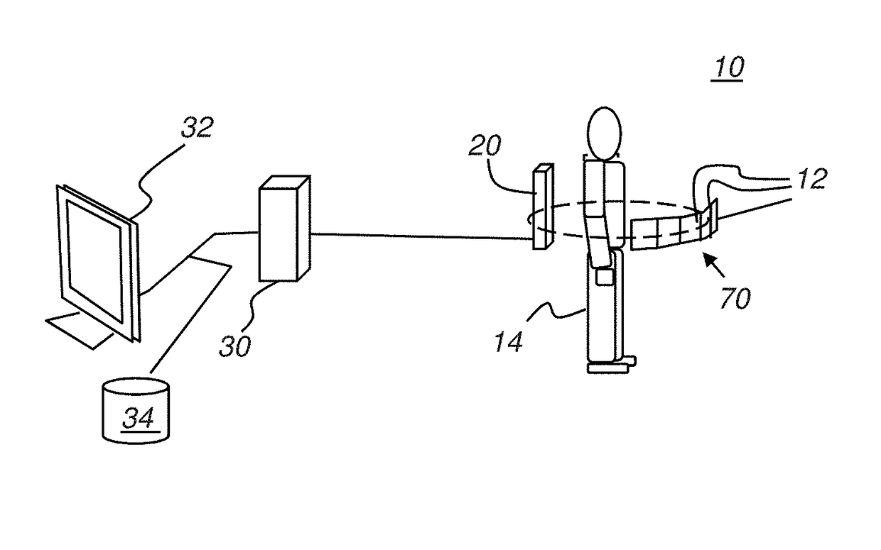
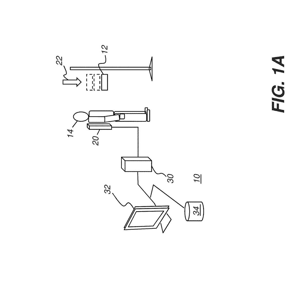
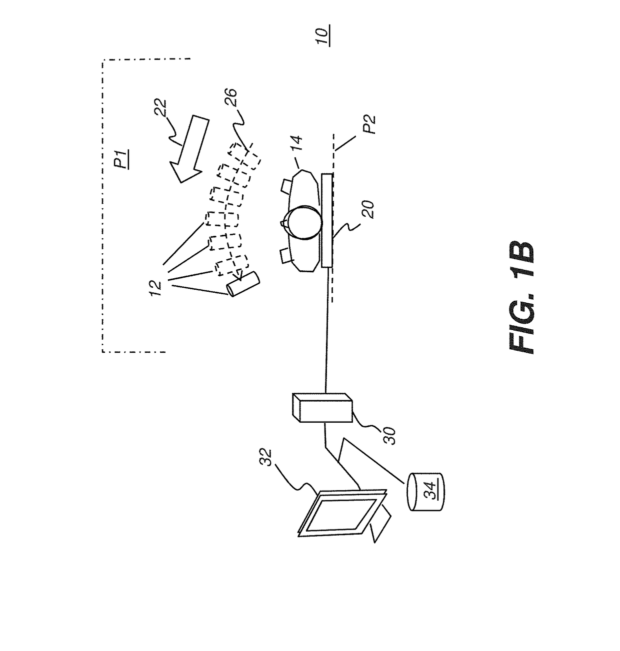
[0031]The following is a detailed description of the preferred embodiments, reference being made to the drawings in which the same reference numerals identify the same elements of structure in each of the several figures.

[0032]Where they are used herein, the terms “first”, “second”, and so on, do not necessarily denote any ordinal, sequential, or priority relation, but are simply used to more clearly distinguish one element or set of elements from another, unless specified otherwise.

[0033]In the context of the present disclosure, the terms “viewer”, “operator”, “viewing practitioner”, “observer”, and “user” are considered to be equivalent and refer to the viewing practitioner or other person who views and manipulates an x-ray image on a display monitor or other viewing apparatus.

[0034]As used herein, the term “energizable” relates to a device or set of components that perform an indicated function upon receiving power and, optionally, upon receiving an enabling signal.

[0035]The term...


PUM


Abstract

A method for tomosynthesis volume reconstruction acquires at least a prior projection image of the subject at a first angle and a subsequent projection image of the subject at a second angle. A synthetic image corresponding to an intermediate angle between the first and second angle is generated by a repeated process of relating an area of the synthetic image to a prior patch on the prior projection image and to a subsequent patch on the subsequent projection image according to a bidirectional spatial similarity metric, wherein the prior patch and subsequent patch have n×m pixels; and combining image data from the prior patch and the subsequent patch to form a portion of the synthetic image. The generated synthetic image is displayed, stored, processed, or transmitted.

Description

FIELD OF THE INVENTION[0001]The present disclosure relates to digital tomosynthesis imaging and more particularly to methods and apparatus for maintaining image quality while reducing the number of projection images obtained.BACKGROUND OF THE INVENTION[0002]Digital tomosynthesis is an imaging technique that provides three-dimensional (3D) patient images, reconstructed from a series of multiple 2D images taken over a succession of angles of the x-ray source relative to the detector. Acquisition of the 2D projection images used for tomosynthesis employs a large-area digital detector, such as a digital detector that is typically used for conventional single projection radiography.[0003]In conventional tomosynthesis, a single X-ray source is moved along a generally linear scan path for generating multiple exposures. The set of projection image data that is acquired with tomosynthesis, by comparison, with full volume image information obtained using computed tomography (CT) or full volum...

Claims


Application Information

Patent Timeline
Patent Type & Authority Applications(United States)
IPC IPC(8): G06T11/00A61B6/00A61B6/02
CPCG06T11/008A61B6/5264A61B6/025A61B6/027A61B6/5205A61B6/542
Inventor VOGELSANG, LEVON O.RAY, LAWRENCE A.SIMON, RICHARD A.
Owner CARESTREAM HEALTH INC
Why Eureka
Try Eureka