
Facility and Process for the Recycling of Biomaterial

a biomaterial and recycling technology, applied in biochemistry equipment, biochemistry equipment and processes, applications, etc., can solve the problems of high technical and procedural expenditure, carbon and structural materials, and difficult thermophilic fermentation of highly nitrogenous wastes, and achieve the effect of improving process control and particularly economical biomaterial recycling

Active Publication Date: 2017-09-21
EISENMANN SE
View PDF17 Cites 2 Cited by
  • Summary
  • Abstract
  • Description
  • Claims
  • Application Information

AI Technical Summary

Benefits of technology

The present invention provides a facility for economically recycling biomaterial with improved process control. The facility includes a hygiene stage with a hygienization chamber for receiving and thermal hygienization of biomaterial discharged from fermentation. This guarantees reliable hygienization even at low fermentation temperatures. The downstream separation of fermentation residue into a fluid phase and solid phase can be omitted through composting and heating of the fluid phase. The fermentation chamber is configured as a reactor with plug flow, which brings about increased load-bearing capacity and improved biodegradation level and hygienizability of the biomaterial.

Problems solved by technology

Since the thermophilic fermentation of highly nitrogenous wastes is extremely difficult, dilution water and / or dilution substrate, which entail high technical and procedural expenditures, are accordingly generally used.
During composting, however, the lack of carbon and structural material, in particular, can lead to difficulties.
The disadvantages of the known process may, for example, be the relatively high expense for equipment or technical and procedural expenditures, as the case may be, as well as the relatively low level of recycling that is achieved during the processing of the biomaterial.

Method used


Image

  • Facility and Process for the Recycling of Biomaterial
  • Facility and Process for the Recycling of Biomaterial
  • Facility and Process for the Recycling of Biomaterial

Examples


Embodiment Construction

[0029]While this invention is susceptible to embodiments in many different forms, there is described in detail herein, preferred embodiments of the invention with the understanding that the present disclosures are to be considered as exemplifications of the principles of the invention and are not intended to limit the broad aspects of the invention to the embodiments illustrated.

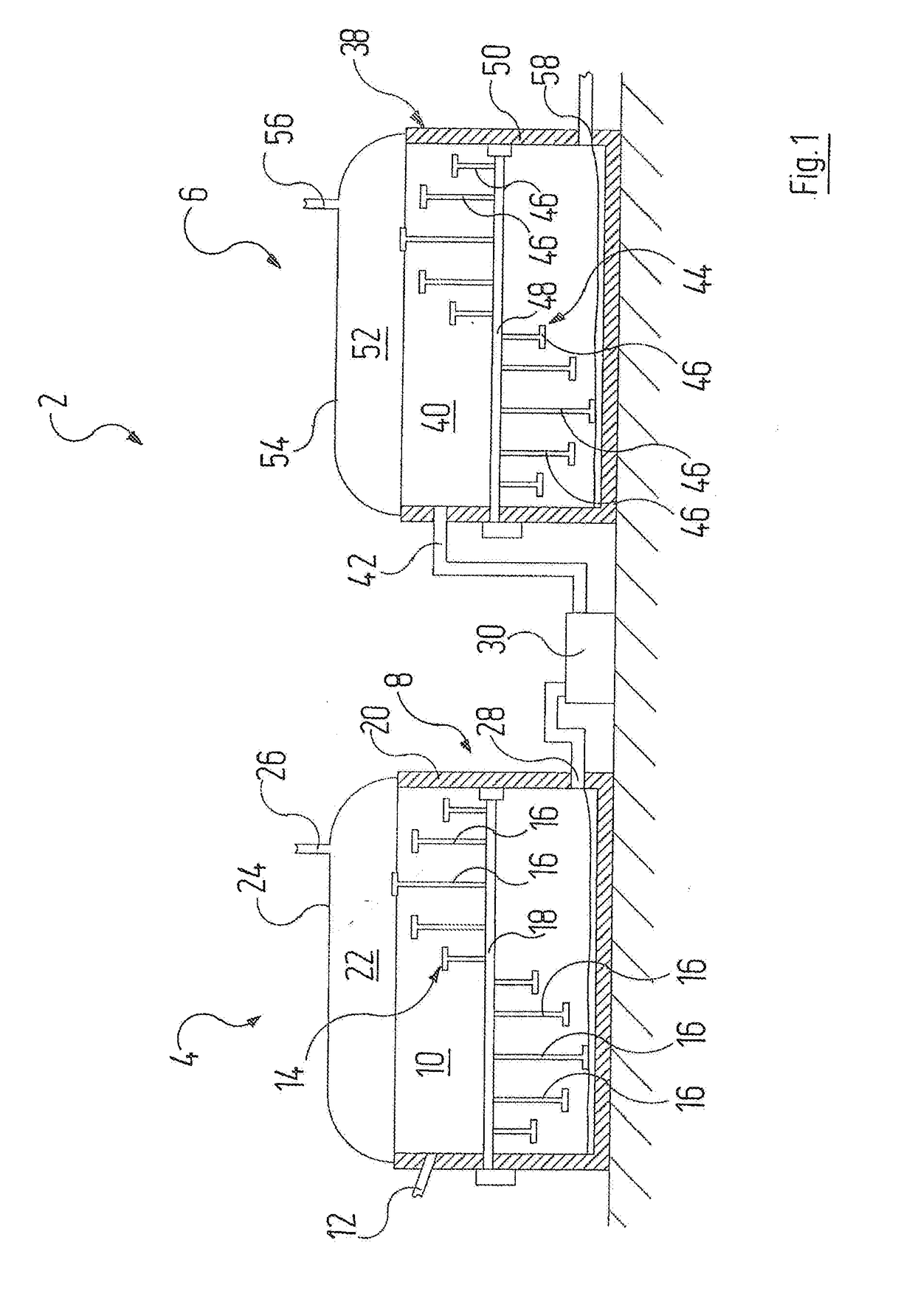
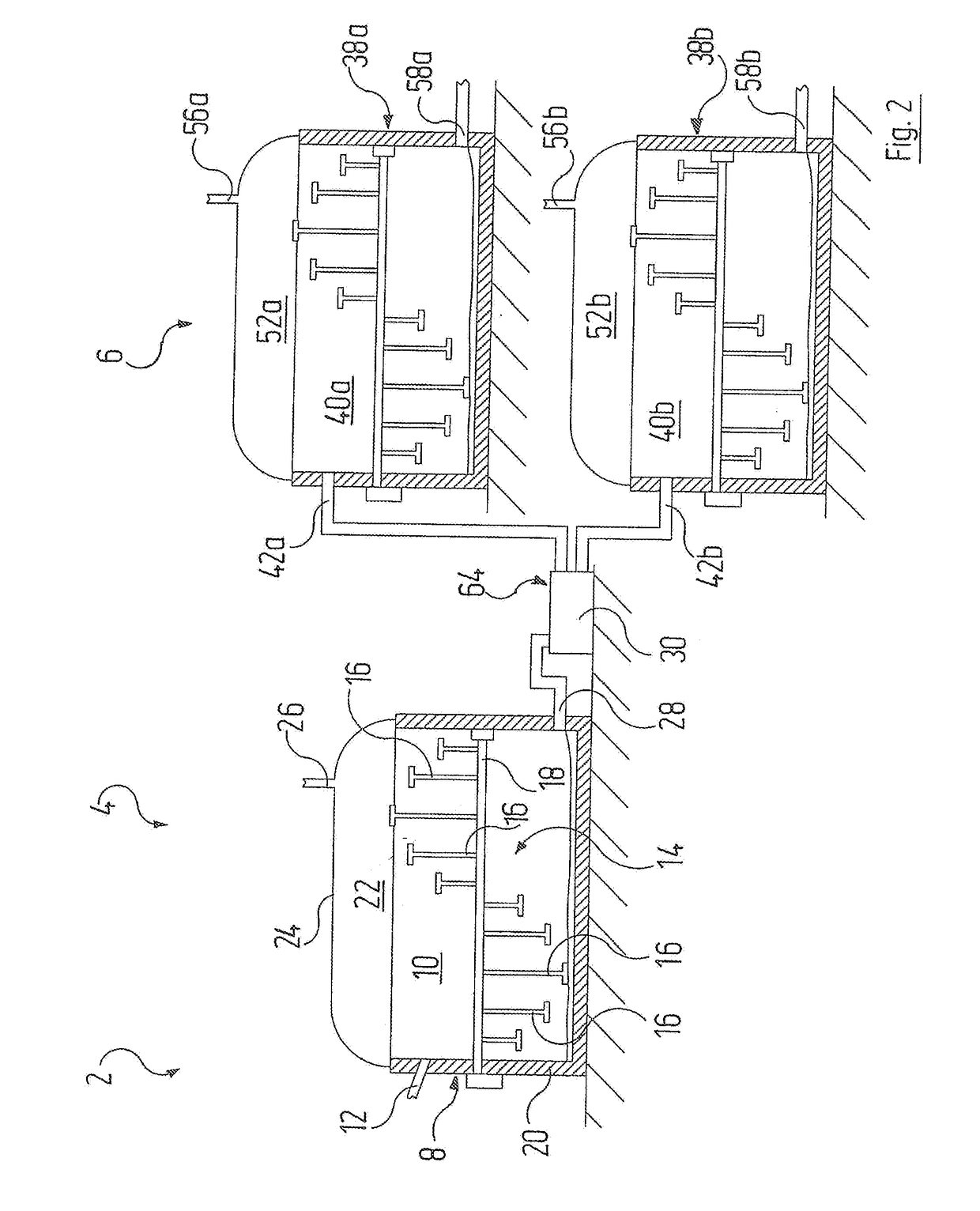
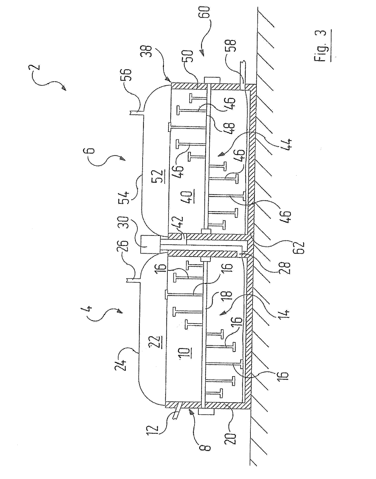
[0030]FIG. 1 depicts a part of a facility 2 for the recycling of biomaterial with a fermentation stage 4, and a hygiene stage 6.

[0031]The fermentation stage 4 is equipped with a container 8, which is also termed a fermentation container, and which has a fermentation chamber 10 for the production of biogas through anaerobic fermentation of the biomaterial. The container 8 of the fermentation stage 4 has a feeding device 12, which is configured to bring biomaterial into the fermentation chamber 10. Biomaterial, which is conveyed to the fermentation with the help of the feeding device 12, can, in particular, be...


PUM

PropertyMeasurementUnit
temperatureaaaaaaaaaa
volumeaaaaaaaaaa
structureaaaaaaaaaa

Abstract

A facility for the recycling of biomaterial with a fermentation stage, whereby the fermentation stage has a fermentation chamber for the production of biogas through anaerobic fermentation of the biomaterial, and with a hygiene stage that is positioned downstream from the fermentation stage, whereby the hygiene stage has a hygienization chamber for the reception and the thermal hygienization of biomaterial discharged from the fermentation stage. A process for the recycling of biomaterial by zymosis is also provided, whereby biogas is produced in a fermentation stage through anaerobic fermentation of the biomaterial, whereby the biomaterial is, after flowing through the fermentation stage, conveyed to a hygiene stage in which the biomaterial thermal is hygienized, and whereby the biomaterial is, after flowing through the hygiene stage, made available as recyclable agricultural, hygienized fermentation residue.

Description

RELATED APPLICATION[0001]The present application claims priority to German Application No. 10 2016 003 256.1 filed Mar. 16, 2016—the contents of which are fully incorporated herein by reference.FIELD OF THE INVENTION[0002]The invention relates to a facility for the recycling of biomaterial with a fermentation stage, whereby the fermentation stage has a fermentation chamber for the production of biogas through anaerobic fermentation of the biomaterial.[0003]The invention also relates to a process for the recycling of biomaterial through zymosis, whereby biogas is produced in a fermentation stage through anaerobic fermentation of the biomaterial.BACKGROUND OF THE INVENTION[0004]DE 195 16 378 A1 describes a process for the fermentation of organic residual materials with a thermophilic biogas reactor. Since the thermophilic fermentation of highly nitrogenous wastes is extremely difficult, dilution water and / or dilution substrate, which entail high technical and procedural expenditures, ...

Claims


Application Information

Patent Timeline
Patent Type & Authority Applications(United States)
IPC IPC(8): C05F17/00C05F17/02C12M1/00
CPCC05F17/009C05F17/0258C12M29/00C12M23/58C12M21/04C12M27/06C12M47/16C12M47/20C12P5/023Y02P20/145C05F17/964C05F17/80Y02E50/30Y02W30/40
Inventor SCHLUETER, THOMAS
Owner EISENMANN SE
Learn More