
Method for recording a complete projection data set in the central layer for ct reconstruction using a c-arm x-ray apparatus with a limited rotation range

a technology of c-arm x-ray and central layer, which is applied in the field of carm x-ray imaging systems, can solve the problems of increasing the risk of collision with other apparatuses, reducing the working space of persons participating in intervention, and affecting the diagnosis of the conditions in the roi. it and the c-arm x-ray apparatus with an increased radius is bulkier and heavier. it is therefore more difficult to handle and maneuver

Active Publication Date: 2017-09-21
ZIEHM IMAGING
View PDF2 Cites 3 Cited by
  • Summary
  • Abstract
  • Description
  • Claims
  • Application Information

AI Technical Summary

Benefits of technology

Enables the recording of a complete projection data set with reduced space requirements and improved mobility of the C-arm X-ray apparatus, minimizing artifacts in the reconstructed X-ray volume while maintaining effective 3D reconstruction capabilities.

Problems solved by technology

Each movement component perpendicular to the original C-arm plane would increase the space requirement of the C-arm X-ray apparatus in the direction of the longitudinal axis of the patient bench and generate an increased risk of collision with other apparatuses and / or reduce the working space for the persons participating in the intervention.
If a disk-shaped X-ray volume is reconstructed from an incomplete projection data set, then artifacts occur in the reconstructed X-ray volume, which strongly interfere with a diagnosis of the conditions in the ROI.
A C-arm X-ray apparatus with an increased radius is bulkier and heavier and consequently more difficult to handle and maneuver than a compact, mobile C-arm X-ray apparatus with a C-arm length of 180° and a smaller radius with the same opening width.
The methods for recording a scan for generating a projection data set with a C-arm X-ray apparatus with cone beam geometry that are known in the prior art, and wherein the apparatus in the plane of the C-arm has a fan beam geometry with a fan angle and the C-arm of which during the scan is moved in a space-fixed plane, have the disadvantage that a complete set of X-ray projections for the analytical reconstruction of a disk-shaped X-ray volume located in the plane of the C-arm requires an orbital angle adjustment range of at least 180°.

Method used


Image

  • Method for recording a complete projection data set in the central layer for ct reconstruction using a c-arm x-ray apparatus with a limited rotation range
  • Method for recording a complete projection data set in the central layer for ct reconstruction using a c-arm x-ray apparatus with a limited rotation range
  • Method for recording a complete projection data set in the central layer for ct reconstruction using a c-arm x-ray apparatus with a limited rotation range

Examples


Embodiment Construction

[0043]Preferred embodiments of the invention are explained with reference to the figures.

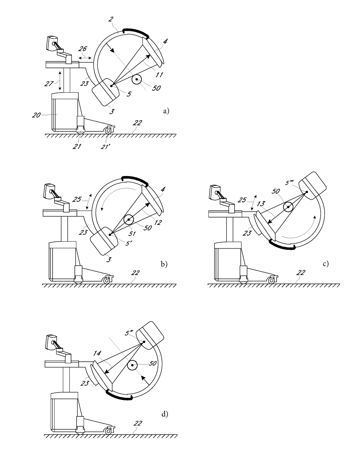
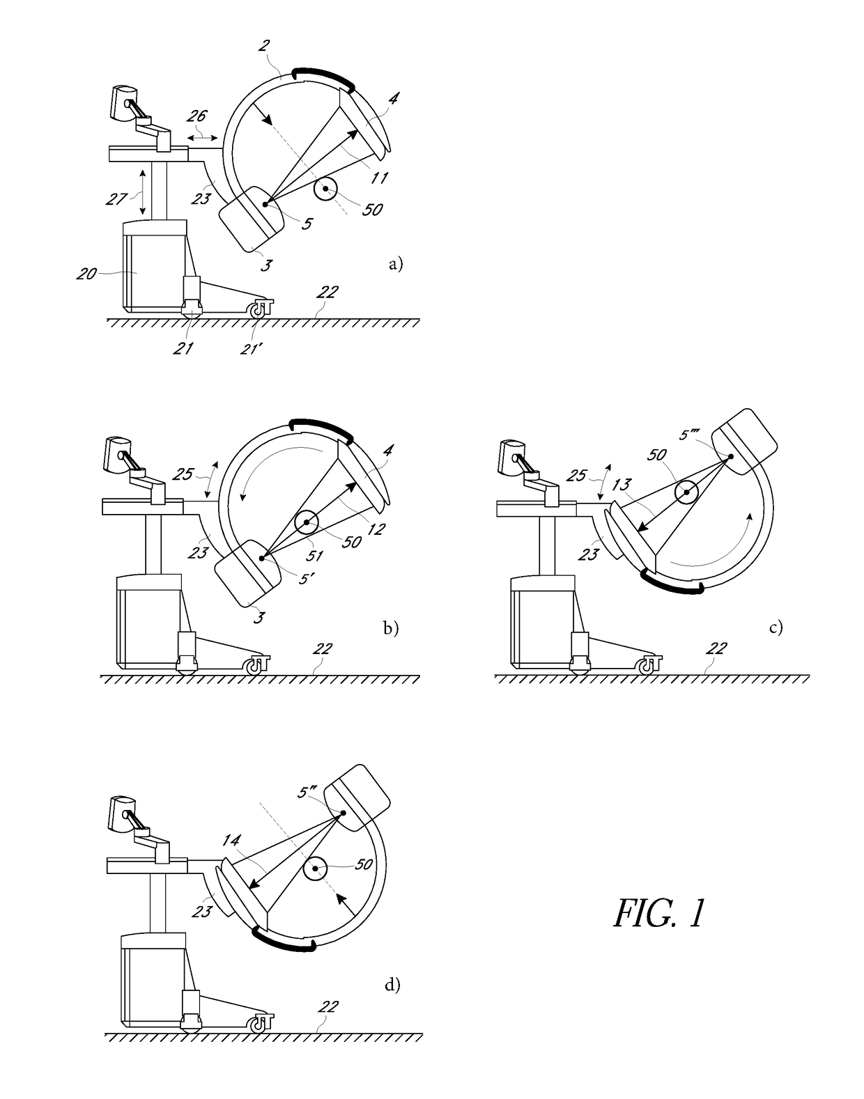
[0044]In FIG. 1, a C-arm X-ray apparatus 1 with a limited rotation range is represented in four different phases of the recording process for recording a complete projection data set for a region of interest (“ROI”) 50. The example of a C-arm X-ray 1 of FIG. 1 shows an apparatus carriage 20 that can be moved by means of wheels 21, 21′ along the floor 22. However, in some embodiments of the invention, it is also provided to mount the C-arm 2 on a stationary floor or ceiling tripod in an adjustable manner.

[0045]The C-arm of FIG. 1 is a non-isocentric C-arm, in which the circle center of the C is not on the central ray vector 11, 12, 13, 14. In order to be able to record a rotation scan of an examination object with a ROI, the holder 23 of the C-arm 2 is adjusted during the scan in correlation with the orbital movement in the orbital movement axis 25 in the plane of the C-arm 2, in such a manner th...


PUM


Abstract

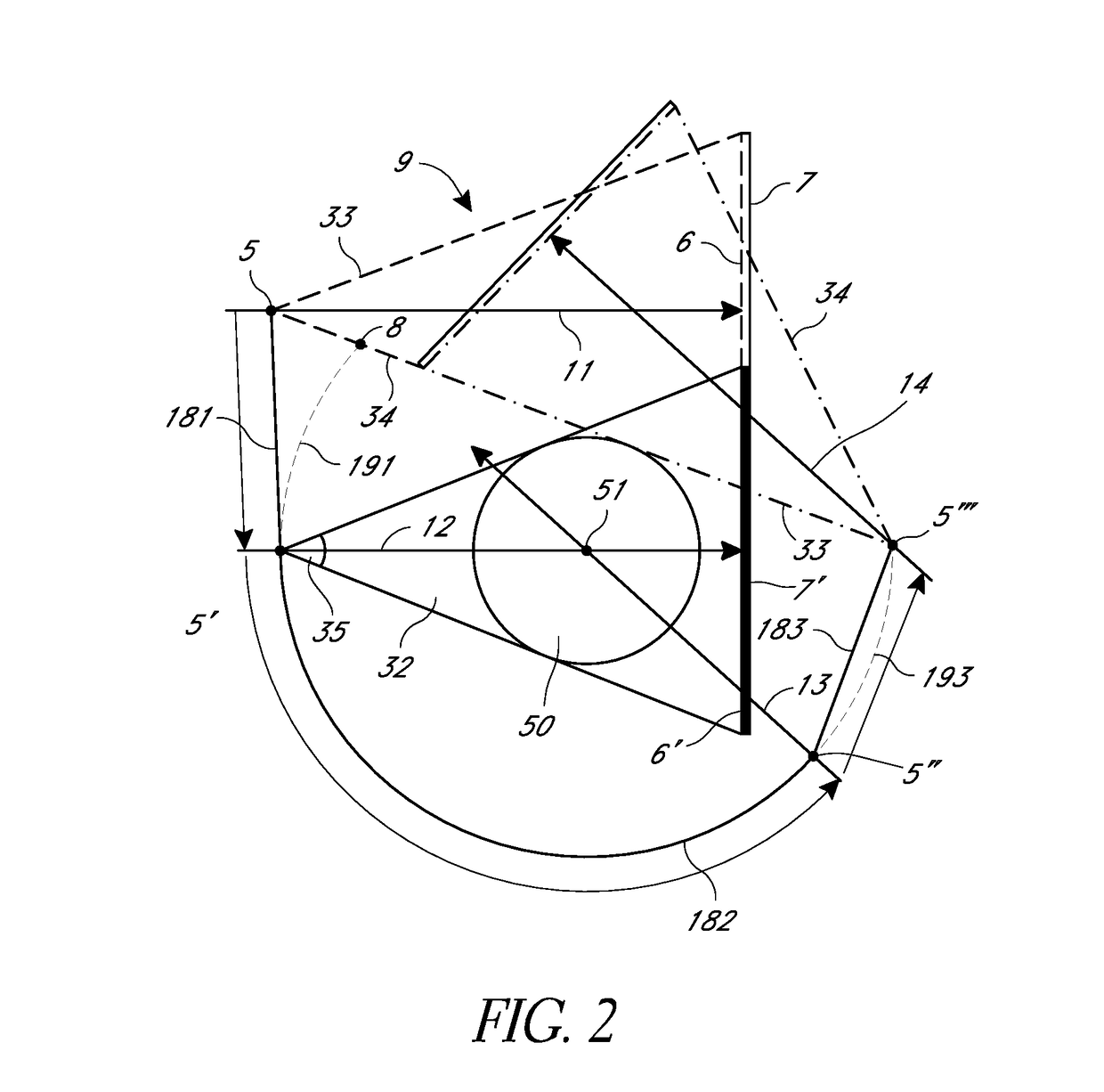
A method for recording a scan from a series of 2D X-ray projections using a C-arm X-ray apparatus allows an analytical volume reconstruction of a disk-shaped region of interest. The C-arm X-ray apparatus has a coherent, flat focus trajectory comprising three sections on which the focus of the X-ray source is moved with recording of X-ray projection views. The X-ray source emits a cone beam in the direction of an imaging X-ray detector, such as in particular a flat panel detector FPD. In some implementations, the cone beam is configured as a fan beam with a fan angle in the plane of the focus trajectory, which contains the ROI with the virtual scan center in its center, wherein the central ray of the fan beam is located on the bisector of the fan angle, and stands vertically on the ray inlet window. Before the beginning of the scan, the C-arm is positioned in the orbital movement axis in a first extreme position in which the holder engages at one end of the C-arm with the X-ray source, and the adjustable holder of the C-arm is positioned in such a manner that the ROI is located outside of the circle segment formed by the C-arm and the central ray, and a first limiting beam of the fan beam, which starts from the focus point and which is located on the side of the central ray facing away from the C-arm, is tangential to the ROI. During the recording of the scan, the plane of the C-arm remains fixed in space.

Description

INCORPORATION BY REFERENCE TO ANY PRIORITY APPLICATIONS[0001]Any and all applications for which a foreign or domestic priority claim is identified in the Application Data Sheet as filed with the present application are hereby incorporated by reference under 37 CFR 1.57.BACKGROUND OF THE INVENTION[0002]Field of the Invention[0003]The present invention relates to C-arm X-ray imaging systems, and in particular, relates to methods for recording scans in a region of interest for CT reconstruction using C-arm X-ray imaging systems.[0004]Description of the Related Art[0005]In interventional X-ray diagnostics, mobile C-arm X-ray apparatuses are being used to an increasing extent. Such a C-arm X-ray apparatus is movable on the floor and it carries, on a chassis, a multiply adjustable holder in which a circular arc-shaped C-arm can be adjusted along its periphery in an orbital movement, wherein the C-arm carries an X-ray source at one end and an imaging X-ray detector at the other end, prefer...

Claims


Application Information

Patent Timeline
Patent Type & Authority Applications(United States)
IPC IPC(8): A61B6/03A61B6/00H05G1/02
CPCA61B6/4078A61B6/4405A61B6/4441A61B6/5205H05G1/02A61B6/035A61B6/4028
Inventor RITSCHL, LUDWIG
Owner ZIEHM IMAGING
Learn More