Upright walker having a user safety system employing haptic feedback
a safety system and upright walker technology, applied in the field of smart upright walker, can solve the problems of difficulty in smooth transition of irregular terrain, lack of upper body and arm support, and significant hand and arm strength to maneuver and operate hand brakes, so as to improve stability and safety, improve posture and comfort, and support the upper body of the user.
- Summary
- Abstract
- Description
- Claims
- Application Information
AI Technical Summary
Benefits of technology
Problems solved by technology
Method used
Image
Examples
embodiment 149
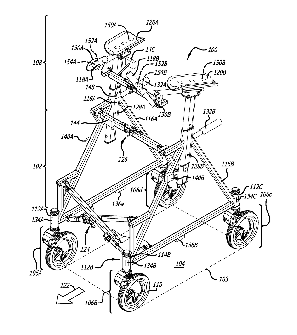
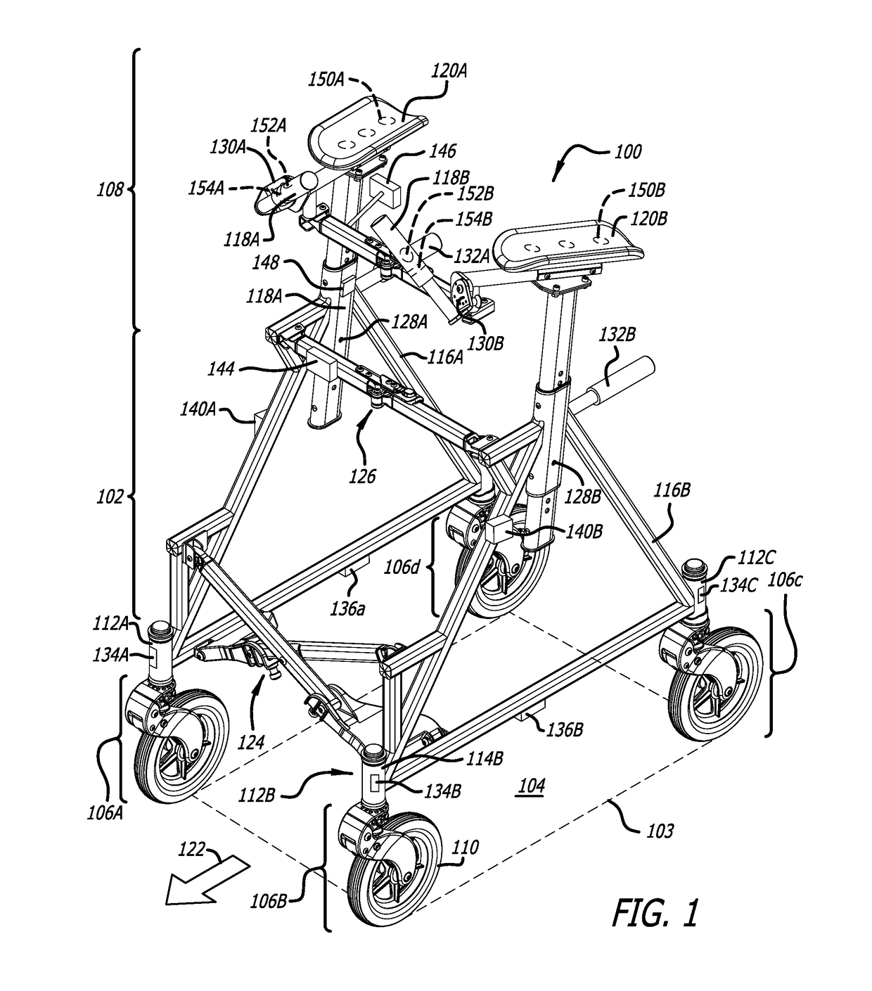
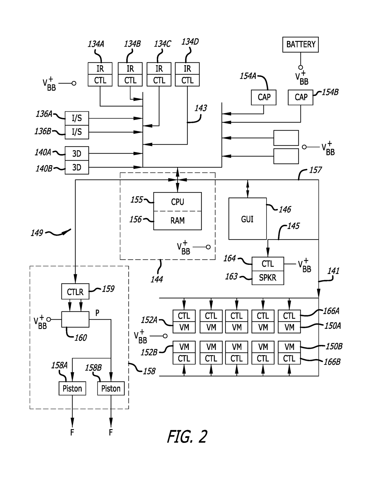
[0058]FIG. 2 is a functional block diagram of an exemplary walker control system embodiment 149 illustrating the relationship among several control system elements and signals provided for automatic obstacle avoidance and user safety in an exemplary walker embodiment. The various elements are labeled with the numerals used above with respect to FIG. 1. Additionally, system controller assembly 144 includes a microprocessor 155, with a Random Access Memory (RAM) 156 coupled by means of a digital data bus 157 to GUI 146 and the other elements substantially as shown. One such element is the electrohydraulic braking system 158 coupled to data bus 157, which includes a braking controller 159, a hydraulic system 160 for producing pressure in a hydraulic line 161, and a plurality of caliper pistons 162A-B each disposed to impose a braking force on a respective caliper assembly (see FIGS. 13-14). Handle touch sensors 154A-B are each shown producing a user touch signal that is coupled to micr...
embodiment 182
[0066]FIG. 9 is a block diagram illustrating the operation of a first alternative walker control system embodiment 182. A plurality of walker sensors each produce a digital sensor output signal, exemplified by the digital sensor output signal 184A, responsive to a respective sensor input (not shown), such as an input to (see FIGS. 1-2) optical sensor 148, handle touch sensor 154A, incline sensor 136A or Doppler microwave sensor 134A, for example without limitation. These digital sensor output signals are coupled by means of a data bus 186 to the microprocessor 188 in any useful manner known in the art. Microprocessor 188 produces a digital control output signal 190 responsive to the digital sensor input signals on data bus 186 according to program instructions (not shown) stored in a RAM 192. Digital control output signal 190 is transferred by data bus 186 to a kinetic motor driver 194, which produces a kinetic motor driver signal 196. Kinetic motor driver signal 196, which may be a...
PUM
 Abstract
Description
Claims
Application Information
 - R&D
- Intellectual Property
- Life Sciences
- Materials
- Tech Scout
- Unparalleled Data Quality
- Higher Quality Content
- 60% Fewer Hallucinations
Browse by: Latest US Patents, China's latest patents, Technical Efficacy Thesaurus, Application Domain, Technology Topic, Popular Technical Reports.
© 2025 PatSnap. All rights reserved.Legal|Privacy policy|Modern Slavery Act Transparency Statement|Sitemap|About US| Contact US: help@patsnap.com


