
Method for rendering multi-channel audio signals for l1 channels to a different number l2 of loudspeaker channels and apparatus for rendering multi-channel audio signals for l1 channels to a different number l2 of loudspeaker channels

a multi-channel audio signal and loudspeaker technology, applied in the direction of electrical equipment, stereophonic systems, etc., can solve the problems of high computational complexity, inability to free from artifacts, and the kind of audio rendering is much more expensive in terms of computational complexity,

Active Publication Date: 2017-08-31
DOLBY LAB LICENSING CORP
View PDF3 Cites 17 Cited by
  • Summary
  • Abstract
  • Description
  • Claims
  • Application Information

AI Technical Summary

Benefits of technology

[0022]In one embodiment of the invention, a computer-implemented method for generating an energy preserving mixing matrix G for mixing input channel-based audio signals for L1 audio channels to L2 loudspeaker channels comprises computer-executed steps of obtaining a first mixing matrix Ĝ from virtual source directions and target speaker directions , performing a singular value decomposition on the first mixing matrix Ĝ to obtain a singularity matrix S, processing the singularity matrix S to obtain a processed singularity matrix Ŝ with m non-zero diagonal elements, determining from the number of non-zero diagonal elements a scaling factor α according toa=L1m(forL2≤L1)ora=L2m(forL2>L1),and calculating a mixing matrix G by using the scaling factor according to G=αUŜVT. As a result, the perceived sound, loudness, timbre and spatial impression of multi-channel audio replayed on an arbitrary loudspeaker setup is improved, and in particular comes as close as possible to the original channel based audio as if replayed on its original speaker setup.

Problems solved by technology

This kind of audio rendering is much more expensive in terms of computational complexity, and often not free from artifacts.
One problem is that a consumer's home setup is very likely to use a different placement of speakers due to real world constraints of a living room.

Method used


Image

  • Method for rendering multi-channel audio signals for l1 channels to a different number l2 of loudspeaker channels and apparatus for rendering multi-channel audio signals for l1 channels to a different number l2 of loudspeaker channels
  • Method for rendering multi-channel audio signals for l1 channels to a different number l2 of loudspeaker channels and apparatus for rendering multi-channel audio signals for l1 channels to a different number l2 of loudspeaker channels
  • Method for rendering multi-channel audio signals for l1 channels to a different number l2 of loudspeaker channels and apparatus for rendering multi-channel audio signals for l1 channels to a different number l2 of loudspeaker channels

Examples


Embodiment Construction

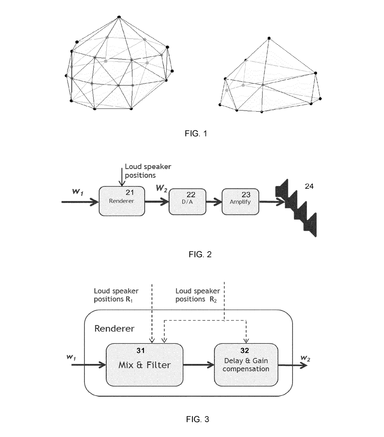
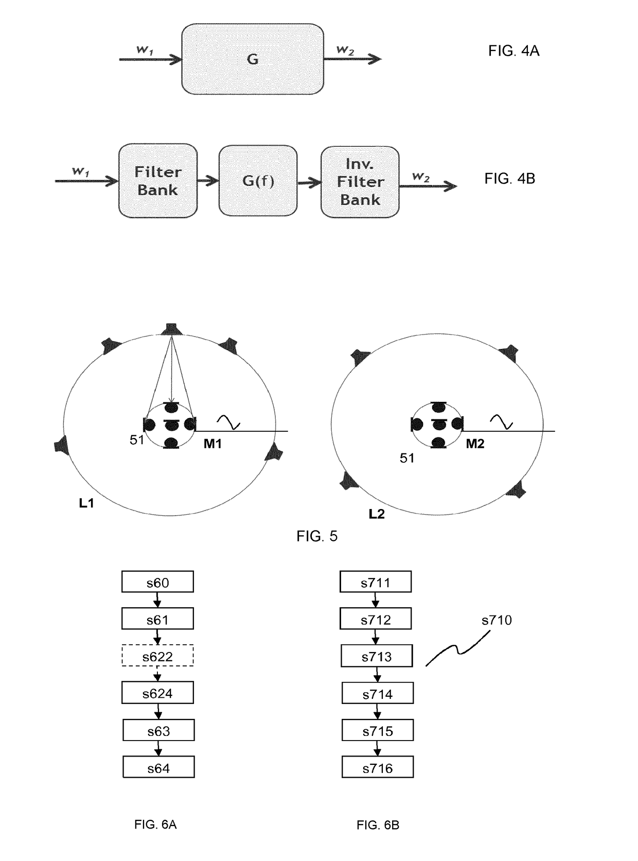
[0040]FIG. 6A shows a flow-chart of a method for rendering a first number L1 of channel-based input audio signals to a different second number L2 of loudspeaker channels according to one embodiment of the invention. The method for rendering L1 channel-based input audio signals w11 to L2 loudspeaker channels, where the number L1 of channel-based input audio signals is different from the number L2 of loudspeaker channels, comprises steps of determining s60 a mix type of the L1 input audio signals, performing a first delay and gain compensation s61 on the L1 input audio signals according to the determined mix type, wherein a delay and gain compensated input audio signal with the first number L1 of channels and with a defined mix type is obtained, mixing s624 the delay and gain compensated input audio signal for the second number L2 of audio channels, wherein a remixed audio signal for the second number L2 of audio channels is obtained, clipping s63 the remixed audio signal, wherein a c...


PUM


Abstract

Multi-channel audio content is mixed for a particular loudspeaker setup. However, a consumer's audio setup is very likely to use a different placement of speakers. The present invention provides a method of rendering multi-channel audio that assures replay of the spatial signal components with equal loudness of the signal. A method for obtaining an energy preserving mixing matrix (G) for mixing L1 input audio channels to L2 output channels comprises steps of obtaining a first mixing matrix Ĝ, performing a singular value decomposition on the first mixing matrix Ĝ to obtain a singularity matrix S, processing the singularity matrix S to obtain a processed singularity matrix Ŝ, determining a scaling factor α, and calculating an improved mixing matrix G according to G=αUŜVT. The perceived sound, loudness, timbre and spatial impression of multi-channel audio replayed on an arbitrary loudspeaker setup practically equals that of the original speaker setup.

Description

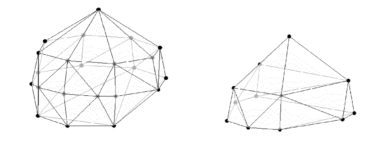
FIELD OF THE INVENTION[0001]This invention relates to a method for rendering multi-channel audio signals, and an apparatus for rendering multi-channel audio signals. In particular, the invention relates to a method and apparatus for rendering multi-channel audio signals for L1 channels to a different number L2 of loudspeaker channels.BACKGROUND[0002]New 3D channel based Audio formats provide audio mixes for loudspeaker channels that not only surround the listening position, but also include channels positioned above (height) and below in respect to the listening position (sweet spot). The mixes are suited for a special positioning of these speakers. Common formats are 22.2 (i.e. 22 channels) or 11.1 (i.e. 11 channels).[0003]FIG. 1 shows two examples of ideal speaker positions in different speaker setups: a 22-channel speaker setup (left) and a 12-channel speaker setup (right). Every node shows the virtual position of a loudspeaker. Real speaker positions that differ in distance to t...

Claims


Application Information

Patent Timeline
Patent Type & Authority Applications(United States)
IPC IPC(8): H04S3/02H04S7/00
CPCH04S3/02H04S2400/03H04S7/308H04S7/301H04S2400/15
Inventor BOEHM, JOHANNES
Owner DOLBY LAB LICENSING CORP
Learn More