
Rotating camera attachment

a technology of rotating camera and camera body, which is applied in the field of rotating camera body, can solve the problems of preventing the viewer from simultaneously recording events, only partially capturing moments based on a very limited field of view,

Inactive Publication Date: 2010-04-13
SUBER III EDWARD H
View PDF11 Cites 40 Cited by
  • Summary
  • Abstract
  • Description
  • Claims
  • Application Information

AI Technical Summary

Benefits of technology

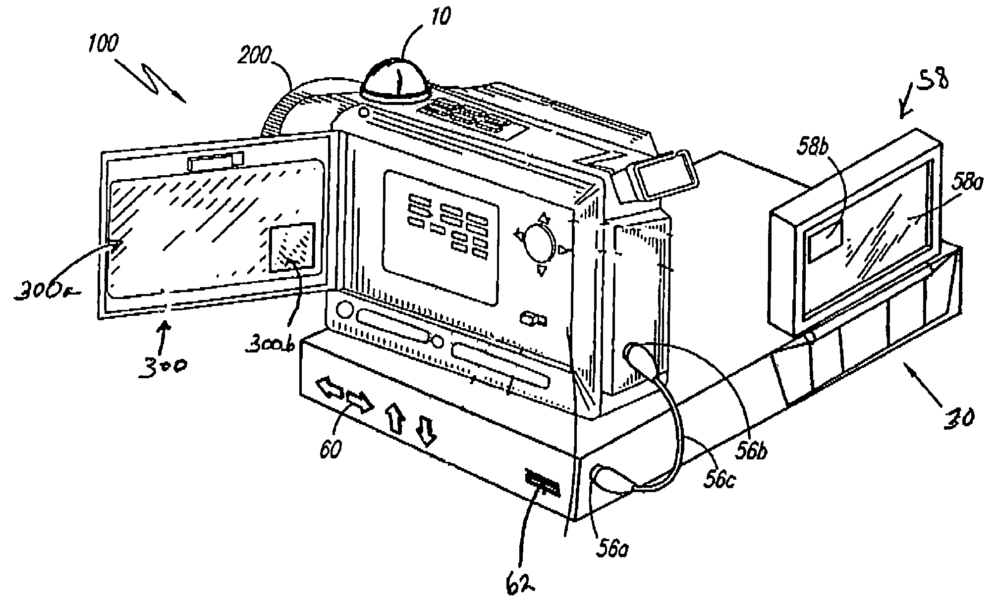
[0023]It is an object of the present invention to provide a means for an event or an object to be captured while the background objects or the supporting objects surrounding the primary object are simultaneously captured. It is an object that a dual-lens camera or camcorder accomplishes the foregoing object, wherein the first lens is a wide-angled lens that captures a primary object in a manner similar to that well known in the camera arts. A second, rotating lens captures the events surrounding the primary object so that a viewer receives a greater impression.
[0026]It is a further object of the present invention that the second lens is a rotatable lens that is adapted to attach to after-market cameras so that a person may easily secure it to an existing camera and convert it to a dual-lens recording system at the times he or she desires. It is an object that the present invention is not so obtrusive, complex or expensive that it makes it an unattractive means to capture a special event.
[0027]It is a final object of the present invention to provide all of the advantages the foregoing objects entail.

Problems solved by technology

One disadvantage to this technology is that a person is only able to partially capture a moment based on a very limited field of view typical of most cameras.
The limited fields adequately allow a viewer to record a particular object within view, but they prevent the viewer from simultaneously recording the events that occur around and the ones that react to the primary object.

Method used


Image

  • Rotating camera attachment
  • Rotating camera attachment
  • Rotating camera attachment

Examples


Embodiment Construction

1. Detailed Description of the Figures

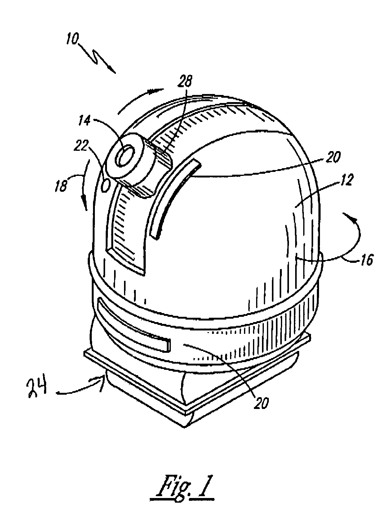
[0034]A rotating camera attachment 10 is shown in FIG. 1, wherein the camera attachment 10 is contained in a housing 12 directly attached to a camera (not shown). The camera attachment 10 comprises a lens 14 that perceives information most preferably in the form of light or infrared information. In its exemplary embodiment, it is preferred that the camera attachment 10 function in a manner similar to that of a typical camera. It is possible that the camera rather function as a still picture camera, a data receiver or any other means of perception.

[0035]The camera attachment 10 has the capability to rotate 360° in a horizontal direction, as shown in the figure by the representative arrow 16. The camera attachment 10 has the additional capability to rotate 180° in a vertical direction, as similarly shown by representative arrow 18. It is preferred that the camera attachment 10 rotate to an approximate 180° to facilitate a proper connection to anot...


PUM


Abstract

The present invention relates generally to a rotatable camera attachment and, more particularly to a rotatable lens system that works in conjunction with after-market digital and video cameras by means of a corresponding electronic device. The rotatable camera attachment comprises a lens that rotates 360° horizontally and 180° vertically to simultaneously capture the images surrounding a primary image recorded with the conventional camera. The electronic device is provided as a means to process the images so they can be viewed together. The instant abstract is neither intended to define the invention disclosed in this specification nor intended to limit the scope of the invention in any way.

Description

RELATED APPLICATIONS[0001]This is a continuation-in-part of U.S. patent application Ser. No. 11 / 098,962 having a filing date of Apr. 5, 2005 now abandoned and which claims priority off U.S. Provisional Patent No. 60 / 560,366 filed on Apr. 8, 2004, both of which are incorporated by reference as if fully rewritten herein.BACKGROUND OF THE INVENTION[0002]1. Field of the Invention[0003]The present invention relates generally to a rotating camera attachment and, more particularly, to a rotatable lens system that works in conjunction with after-market digital and video cameras by means of a corresponding electronic device.[0004]2. Description of the Related Art[0005]Special events have been captured ever since film-based cameras were introduced to the market nearly 100 years ago. The recent advent of digital cameras and digital camcorders enhances a person's ability to easily and inexpensively capture events in more striking detail. One disadvantage to this technology is that a person is o...

Claims


Application Information

Patent Timeline
IPC IPC(8): H04N5/232H04N5/225
CPCH04N5/2252H04N7/183H04N5/23238H04N5/2259H04N23/51H04N23/58H04N23/698
Inventor SUBER, III, EDWARD H.HAWES, DANA
Owner SUBER III EDWARD H
Learn More