
Friction welding

Inactive Publication Date: 2017-08-31
ROLLS ROYCE PLC
View PDF7 Cites 5 Cited by
  • Summary
  • Abstract
  • Description
  • Claims
  • Application Information

AI Technical Summary

Benefits of technology

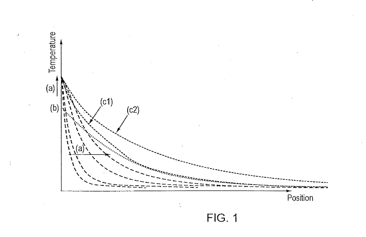
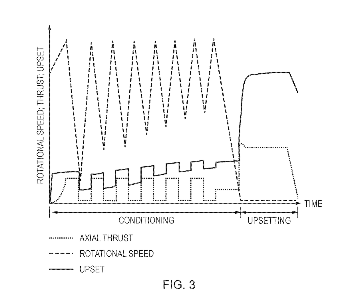
The patent text suggests that controlling the energy input during the friction-based trial and error process can improve the quality of the weld achieved after upset. By controlling the energy input, a pre-determined temperature profile can be generated in the shear zone, which can prevent parts of the shear zone from experiencing temperatures and pressures that cause undesirable phase transformations during conditioning. This pre-conditioning phase can bring the weld zone of the components to a state where viscoplasticity can be achieved using conventional equipment, and can help achieve a stable burn-off and a good quality weld with subsequent application of an upsetting force.

Problems solved by technology

Heat generated may be left to dissipate through the shear zone unaided.

Method used


Image

  • Friction welding
  • Friction welding
  • Friction welding

Examples


Embodiment Construction

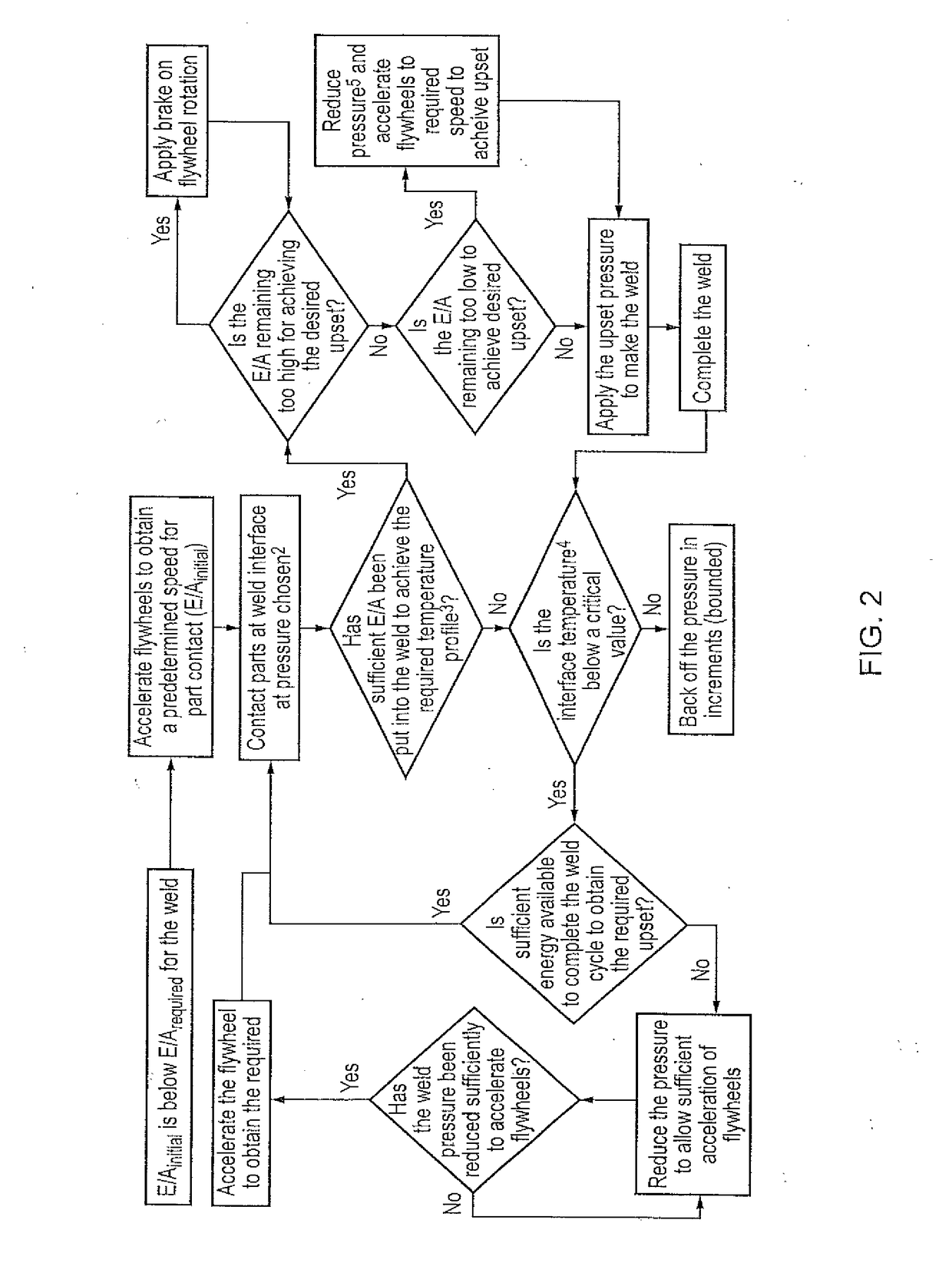
[0048]The following summarises a practical embodiment of the method of the invention using a conventional rotary friction welding machine programmed with an inertia friction weld (IFW) auto-cycle.[0049]1. With weld components aligned, run up the spindle (with / without flywheel)[0050]2. Make one or more contacts between the faying surfaces until the required preheat is met; methods to determine this include but are not limited to:[0051]a. use of thermal measurement (e.g. thermocouples, pyrometry) to monitor temperature and control feedback loop AND / OR[0052]b. modelling to calculate energy input (work done, thermal conductivity, deceleration of flywheels etc.) AND / OR[0053]c. pre-determined cycle / method based on prior knowledge.

[0054]NOTE: The flywheel speed must not drop to below a speed where any time taken to re-spin exceeds a limit required to maintain the desired temperature profile in the part.[0055]3. Decouple or reduce pressure (if required)[0056]4. Adjust spindle speed AND / OR i...


PUM

PropertyMeasurementUnit
Temperatureaaaaaaaaaa
Forceaaaaaaaaaa
Pressureaaaaaaaaaa

Abstract

A method for friction welding of inter alia coarse grain superalloy components, involving conditioning a shear zone of components to be welded by; a) pre-determining temperature profile for which the material of the shear zone of the components approaches viscoplasticity but does not undergo undesirable phase transformations, b) introducing friction at one or both surfaces of the components to be welded to provide a pre-defined quantum of energy sufficient to generate a peak temperature of the temperature profile at that surface whilst simultaneously applying pressure to the surfaces which is below a pressure which will cause upset at the surface, c) withdrawing the friction and / or pressure allowing the heat to disperse by conduction through the shear zone; d) after the temperature at the surface falls below peak temperature, repeating steps b) and c); and repeating step d) as necessary until the pre-determined temperature gradient is achieved throughout the shear zone.

Description

TECHNICAL FIELD[0001]The present invention relates to a friction welding process. More particularly, the invention relates to a friction welding process that is suited to, but not limited to, the joining of high-temperature capable alloys (“Superalloys”).BACKGROUND TO THE INVENTION[0002]Friction welding processes are high integrity joining methods used to fabricate rotating components within gas turbine engines, such as blade integrated discs (blisks), HP, IP, LP discs, drums and shafts in materials such as titanium, nickel superalloys and steel. For manufacture of such components, common friction welding processes include; rotary friction welding (RFW) and linear friction welding (LFW). Examples of rotary friction welding processes are inertia (IFW), direct drive (DDFW), hybrid inertia-direct drive (HFW) and orbital (OFW) methods.[0003]Although one continuous process in practice, several distinct phases are known to play a role in friction welding. In a first phase, welding surface...

Claims


Application Information

Patent Timeline
IPC IPC(8): B23K20/12F01D5/28
CPCB23K20/129B23K20/123B23K20/1225F05D2300/175F05D2220/32F05D2300/133F01D5/28B23K20/12B23K20/24B23K2101/001
Inventor BRAY, SIMON E.WALPOLE, ANDREW R.FORSDIKE, JOHN P. E.BAXTER, GAVIN J.
Owner ROLLS ROYCE PLC
Learn More