
Method for Producing a Prismatic Battery Cell

a technology of prismatic batteries and prismatic cells, which is applied in the direction of batteries, sustainable manufacturing/processing, cell components, etc., can solve the problems of requiring contact with current collectors in the interior of the cell housing and leading current paths through the cell housing to the outside, so as to save material costs, increase capacity, and increase energy density

Inactive Publication Date: 2017-08-17
ROBERT BOSCH GMBH
View PDF1 Cites 0 Cited by
  • Summary
  • Abstract
  • Description
  • Claims
  • Application Information

AI Technical Summary

Benefits of technology

The invention is about a new design for batteries that saves material costs and increases capacity. This is achieved by eliminating the need for an uncoated long electrode edge and only keeping the contact surfaces free of active material. The battery winding is inserted into the cell housing, contact is made with the cathode layer and the anode layer using current collectors, and the cell housing is filled with a liquid electrolyte. A single battery winding with only one cathode layer and one anode layer is used, which reduces welding costs and simplifies the fabrication process. The contour of the current collectors is made easier to produce. The longitudinal sides of the layers with contact surfaces are arranged one above the other in the initial arrangement to ensure electrical insulation. The cathode layer and the anode layer are cut to size using a laser or a punching tool to compensate for any offset in the contact tabs. The invention allows for precise compensation of the offset and reduces no-load voltage (NLOV) and direct current (DC) voltage drop (DV).

Problems solved by technology

This making of contact with the current collectors in the interior of the cell housing and leading the current paths through the cell housing to the outside is very demanding.

Method used


Image

  • Method for Producing a Prismatic Battery Cell
  • Method for Producing a Prismatic Battery Cell
  • Method for Producing a Prismatic Battery Cell

Examples


Embodiment Construction

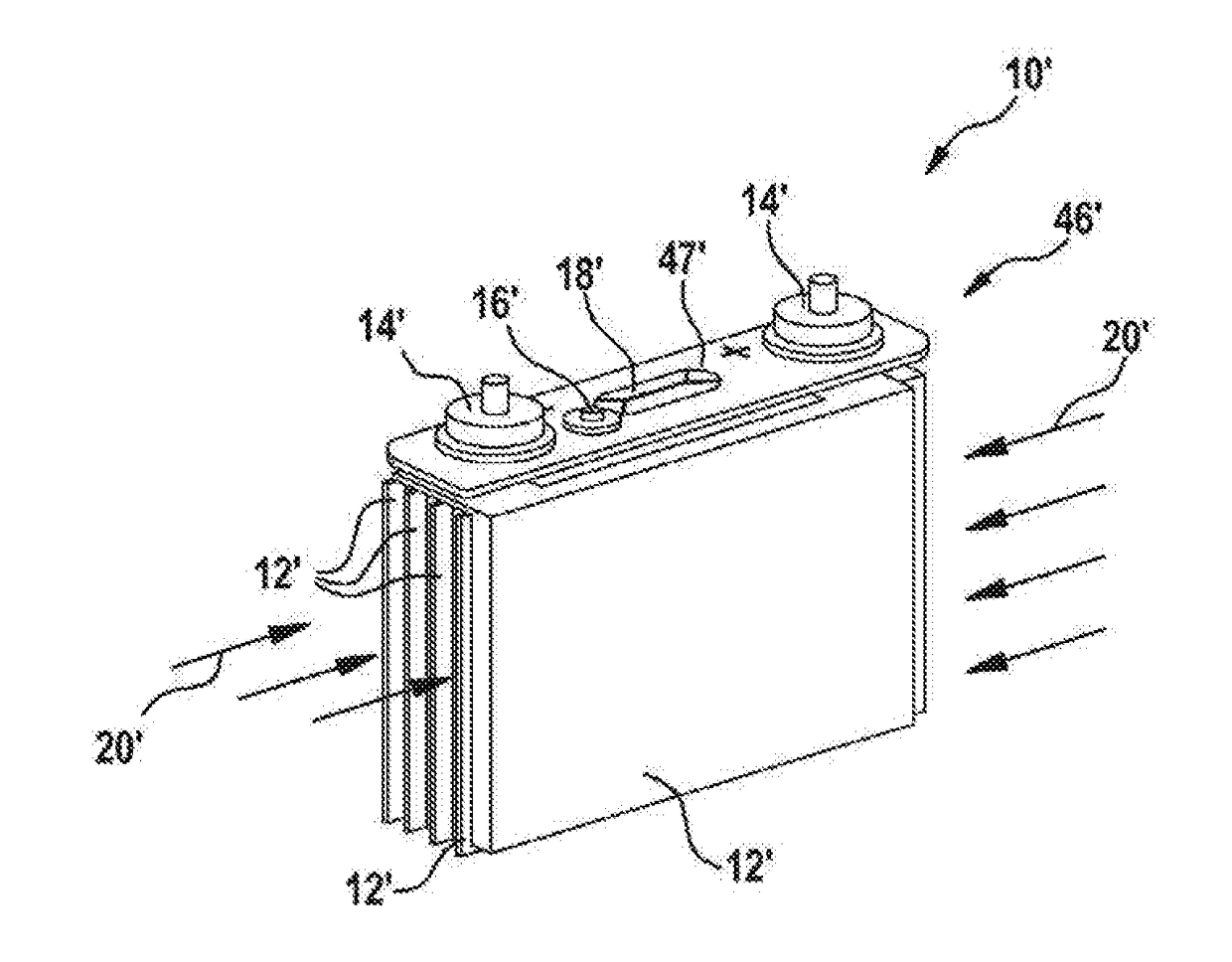
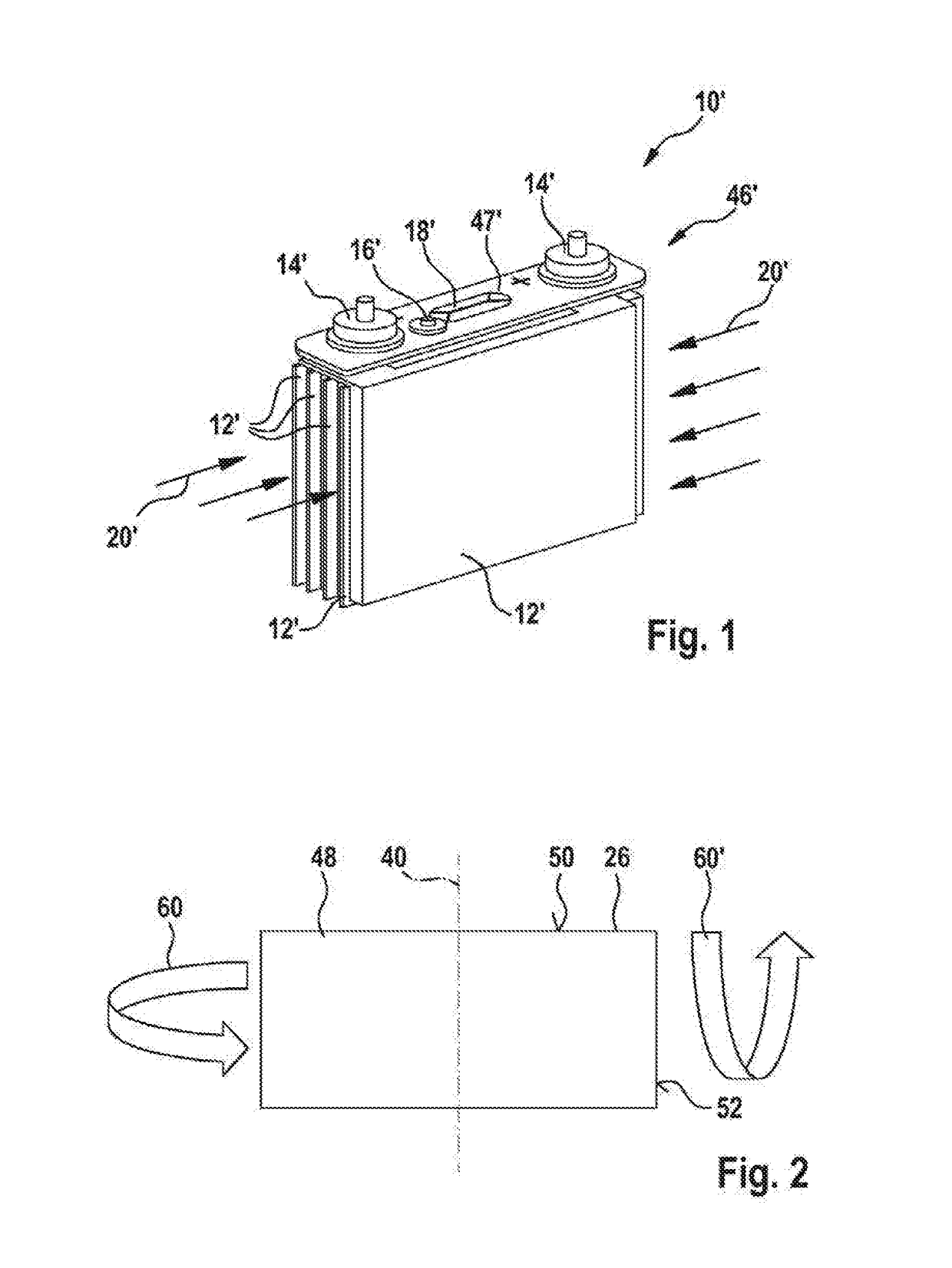
[0037]FIG. 1 shows a prismatic battery cell 10′ in a perspective view according to the prior art.

[0038]The prismatic battery cell 10′ is illustrated without a cell housing, for reasons of clarity, and comprises four battery windings 12′ arranged closely beside one another and a cover group 46′, the cover group 46′ comprising two terminals 14′, by which means electrical contact is made with the prismatic battery cell 10′ from outside.

[0039]The cover group 46′ is additionally assigned a filling opening 16′ and a burst diaphragm 18′. The filling opening 16′ and the burst diaphragm 18′ are located substantially in the center of a terminating plate 47′, whereas the terminals 14′ are placed peripherally on the terminating plate 47′. The battery windings 12′ are inserted into a cell housing and filled with the liquid electrolyte. An inward flow direction 20′ of a liquid electrolyte is indicated by arrows. The liquid electrolyte inFIG. 1 is put in vertically via the filling opening 16′ and ...


PUM

PropertyMeasurementUnit
sizeaaaaaaaaaa
volumeaaaaaaaaaa
negative voltageaaaaaaaaaa

Abstract

A method is used to produce a prismatic battery cell having a cathode layer, an anode layer and two separator layers. The method includes winding an initial arrangement including the cathode layer, the anode layer and the two separator layers around a winding axis to produce a battery winding. The cathode layer and the anode layer each have longitudinal sides and transverse sides and are wound with the transverse sides parallel to the winding axis. The method further includes inserting the battery winding in a cell housing. The method further includes contacting contact surfaces of the cathode layer and the anode layer with current collectors, filling the cell housing with a liquid electrolyte, and closing the cell housing. The cathode layer and the anode layer, on one of their longitudinal sides, are cut to size during their supply to the initial arrangement to form contact surfaces.

Description

PRIOR ART[0001]The invention relates to a method for producing a prismatic battery cell, wherein the battery cell has a cathode layer, an anode layer and at least two separator layers.[0002]The invention also relates to a prismatic battery cell which is produced in accordance with the method, and to a vehicle in which such a prismatic battery cell is installed.[0003]Lithium ion accumulators which are used in the automobile sector often have a prismatic shape for volume utilization reasons. In the interior of a cell housing, for example, there are flat-pressed battery windings (jelly rolls), which are rolled from an anode, a cathode and from separator layers. The cell housing is filled with a liquid electrolyte following the insertion of the battery windings and before the pressure-tight closure. U.S. Pat. No. 8,641,015 B2 provides, for example, such a prismatic battery cell with four battery windings arranged therein.[0004]Making electrical contact with the electrodes, by which the ...

Claims


Application Information

Patent Timeline
Patent Type & Authority Applications(United States)
IPC IPC(8): H01M10/0587H01M10/0525H01M2/26H01M50/538
CPCH01M10/0587H01M2220/20H01M10/0525H01M2/263H01M10/052H01M50/538Y02E60/10Y02P70/50
Inventor BACHER, ANTONIOSEYED ABBASSI, SEYED MOHAMMADKAPLAN, CIHANRIEFLER, MICHAEL
Owner ROBERT BOSCH GMBH
Learn More