
High Dynamic Range Imaging of Environment with a High Intensity Reflecting/Transmitting Source

a high-dynamic range, imaging technology, applied in the field of imaging systems, can solve the problems of affecting the performance of gated and non-gated illumination-based imaging systems, leaking photons, difficult to mask memory nodes, etc., to reduce ambient light accumulation, minimize intense reflection, and minimize frame duration

Active Publication Date: 2017-08-17
BRIGHTWAY VISION
View PDF8 Cites 54 Cited by
  • Summary
  • Abstract
  • Description
  • Claims
  • Application Information

AI Technical Summary

Benefits of technology

The present invention provides an active-gated imaging system for imaging an environment with high-intensity sources. The system includes a light source, a gated camera with an image sensor, a controller, and an image processor. The image sensor includes a pixelated sensor array and an anti-blooming mechanism. The system can identify oversaturated image portions caused by high-intensity sources and interpret them using supplementary image information obtained from low-illumination secondary images. The system can also generate a merged image by combining the main image with the supplementary image information. The invention allows for improved imaging in environments with high-intensity sources and reduces ambient light accumulation in the image frames.

Problems solved by technology

This phenomenon of “leakage photons” is especially problematic in CMOS sensors, where it is difficult to mask the memory node (MN) and floating diffusion in the pixel level sensor (typical masking approaches include: micro-lens focusing light away from the MN, metal layers above the MN, potential attracting the photoelectrons to the photodiode, and potential barriers around the MN).
The presence of highly-reflective sources (e.g., retroreflective signs) and / or highly-transmitting sources (e.g., illuminating objects, such as sunlight or vehicle high beams) in the environment, can adversely affect the performance of both gated and non-gated illumination-based imaging systems.
Due to the excessive intensity of the reflections from such high reflecting / transmitting sources, the resultant image may include portions with extremely high brightness (i.e., appearing overexposed or “washed-out”), rendering the respective features unclear and indecipherable.
The excessive reflections received by the image sensor may also result in a phenomenon known as “blooming”, in which a bright halo appears surrounding the high-reflective object in the reflection-based image, so that other objects in the immediate vicinity are also obstructed from view.
As a result of these saturation and blooming effects, it may be difficult to ascertain with a high degree of confidence the presence of relevant high-reflective / high-transmitting objects in the environment, and to accurately identify whether they pose a potential hazard.
For example, the detection of an oncoming vehicle may be delayed or precluded due to saturated image portions resulting from the vehicle headlights.
The increased time and processing required to accurately determine potential hazards in the vehicle environment also necessitates a longer decision making period, which may increase the likelihood of a traffic accident.
Furthermore, the saturated and bloomed image regions on a displayed image may distract the vehicle driver, and prevent or delay the driver from noticing other important features in the image.
Many CCD and CMOS sensors operate using a linear response, which may result in a higher signal-to-noise ratio (SNR) but are only capable of imaging a limited dynamic range (e.g., under 3 orders of magnitude).

Method used


Image

  • High Dynamic Range Imaging of Environment with a High Intensity Reflecting/Transmitting Source
  • High Dynamic Range Imaging of Environment with a High Intensity Reflecting/Transmitting Source
  • High Dynamic Range Imaging of Environment with a High Intensity Reflecting/Transmitting Source

Examples


first embodiment

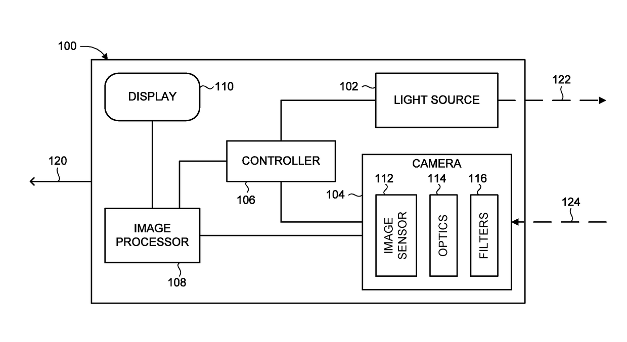
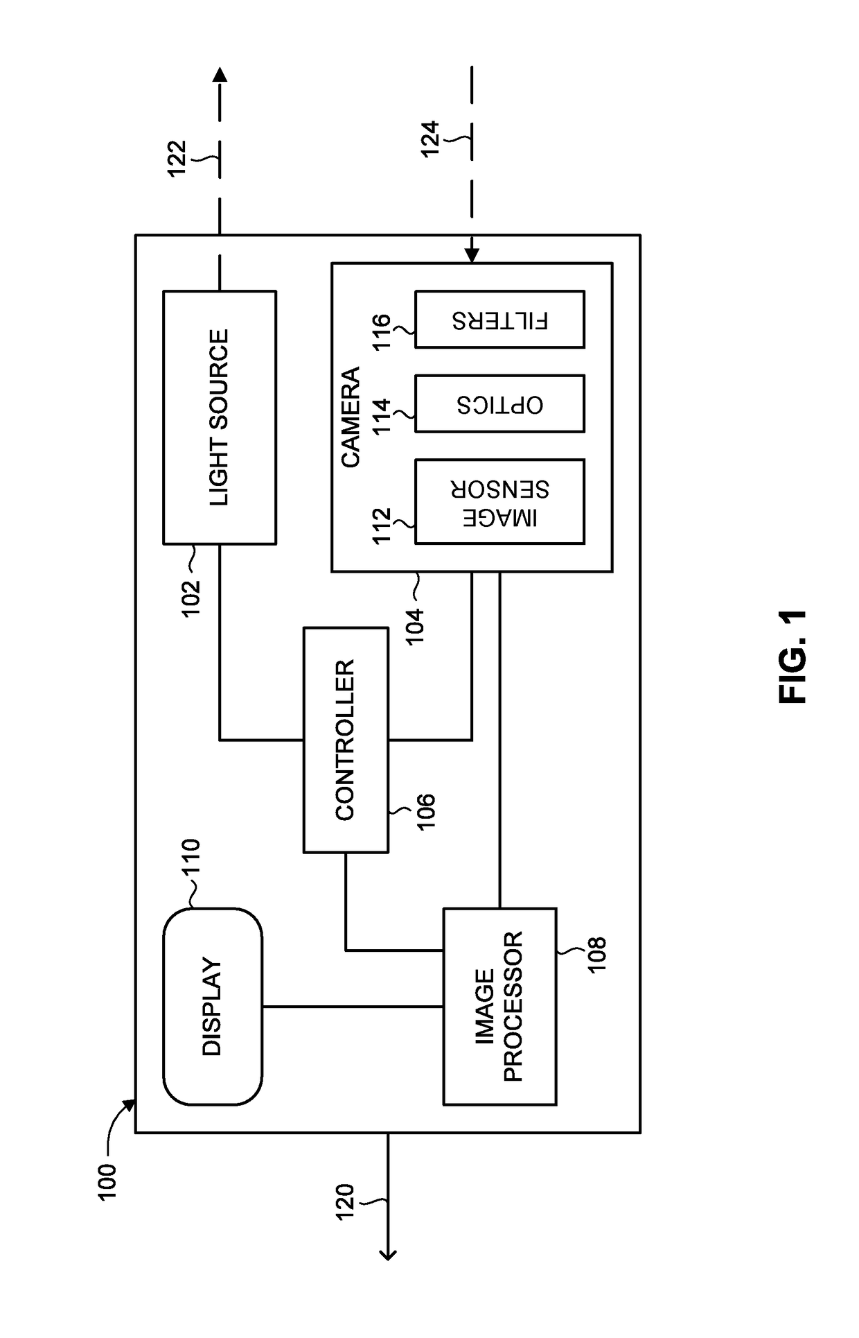
[0041]According to the present invention, the supplementary image information is obtained from a low-illumination secondary image frame acquired using a reduced illumination gating scheme. Reference is now made to FIG. 3, which is an exemplary set of image frames acquired by the imaging system (100) of FIG. 1 when implementing a first approach of supplementary imaging of high-intensity sources, operative in accordance with one embodiment of the present invention. Camera 104 acquires a first image frame (a “main image frame”), referenced 150, using a default gating scheme. Image processor 108 processes image frame 150, and identifies oversaturated image portions 152, 154, 156, arising from high-intensity sources in the imaged environment. Subsequently, camera 104 acquires a secondary image frame, referenced 160, of the same DOF as image frame 150, using a reduced-illumination gating scheme. In particular, the number of gating cycles (i.e., number of transmitted pulses / accumulated ref...

second embodiment

[0042]According to the present invention, the supplementary image information is obtained from low-illumination secondary image content that appears in the acquired image frame due to internal reflections of the reflected pulses between optical elements of the camera. Reference is now made to FIG. 4, which is an exemplary image frame, referenced 180, acquired by the imaging system (100) of FIG. 1 when implementing a second approach of supplementary imaging of high-intensity sources, operative in accordance with another embodiment of the present invention. Camera 104 acquires active-gated image frame 180. Image processor 108 processes image frame 180, and identifies oversaturated image portion 186 arising from a high-intensity source in the imaged environment. Image processor 108 further identifies, in the same image frame 180, a reduced-illumination secondary image portion 188, which contains image content respective of oversaturated image portion 186. In particular, secondary image...

third embodiment

[0043]According to the present invention, the supplementary image information is obtained from a low-illumination secondary image frame acquired by residual photo accumulation when image sensor 112 is in a non-exposure state. Reference is now made to FIGS. 5A and 5B. FIG. 5A is an exemplary first image frame, referenced 190, with oversaturated image portions, acquired by the imaging system (100) of FIG. 1, operative in accordance with a further embodiment of the present invention. FIG. 5B is an exemplary secondary image frame, referenced 200, acquired by the imaging system (100) of FIG. 1, corresponding to the image frame of FIG. 5A, when implementing a third approach of supplementary imaging of high-intensity sources, operative in accordance with a further embodiment of the present invention. Camera 104 acquires a first (“main”) image frame 190 of the environment, which may be gated or non-gated. Image processor 108 processes first image frame 190 and identifies oversaturated image...


PUM


Abstract

Active-gated imaging system and method for imaging environment with at least one high-intensity source. A light source emits light pulses toward the environment, and an image sensor with a pixelated sensor array receives reflected pulses from a selected depth of field and generates a main image. The image sensor exposure mechanism includes a pixelated transfer gate synchronized with the emitted pulses. An image processor identifies oversaturated image portions of the main image resulting from a respective high-intensity source, and interprets the oversaturated image portions using supplementary image information acquired by image sensor. The supplementary information may be obtained from: a low-illumination secondary image having substantially fewer gating cycles than the main image; by accumulating reflected pulses from the high-intensity source after the reflected pulses undergo internal reflections between optical elements of the camera; or a low-illumination secondary image acquired by residual photon accumulation during a non-exposure state of image sensor.

Description

CROSS-REFERENCE TO RELATED APPLICATIONS[0001]This application is a National Phase application filed under 35 U.S.C. §371 of PCT International Application No. PCT / IL2015 / 051028 with an International Filing Date of Oct. 15, 2015, which claims priority to Israel Patent Application No. 235359, filed on Oct. 27, 2014, and U.S. Provisional Patent Application No. 62 / 195,317, filed on Jul. 22, 2015, the entire contents of which are incorporated herein by reference.FIELD OF THE INVENTION[0002]The present invention relates to imaging systems in general, and to active-gated imaging systems for vehicles in particular.BACKGROUND OF THE INVENTION[0003]Night vision imaging systems produce visible images of an environment having minimal ambient light, which would otherwise not be visible to the human eye. Such systems are used by military and law enforcement units, as well as various civilian applications. One such application is for improving the visibility of a vehicle driver during night, rain, ...

Claims


Application Information

Patent Timeline
IPC IPC(8): G01S7/486G01S17/93G01S17/10G01S17/89G01S7/4863G01S17/18G01S17/86G01S17/931
CPCG01S7/4868G01S17/107G01S17/936G01S17/89G01S7/483G01S7/4863B60Q1/14G01S17/18G01S17/86G01S17/931
Inventor GRAUER, YOAVDAVID, OFERLEVI, EYALSONN, EZRIGARTEN, HAIM
Owner BRIGHTWAY VISION
Learn More