Spirometer
a spirometer and spirometer technology, applied in the field of spirometers, can solve the problems of reducing the lifetime of the spirometer, and achieve the effects of convenient, cheap and convenient spirometers, and simple and economical manufacturing methods
- Summary
- Abstract
- Description
- Claims
- Application Information
AI Technical Summary
Benefits of technology
Problems solved by technology
Method used
Image
Examples
third embodiment
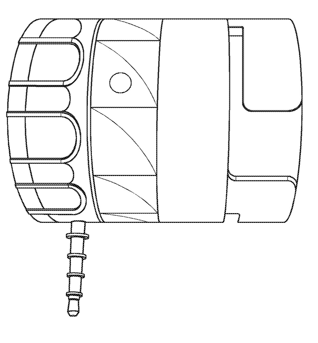
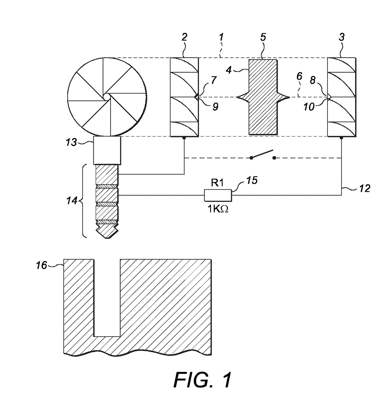
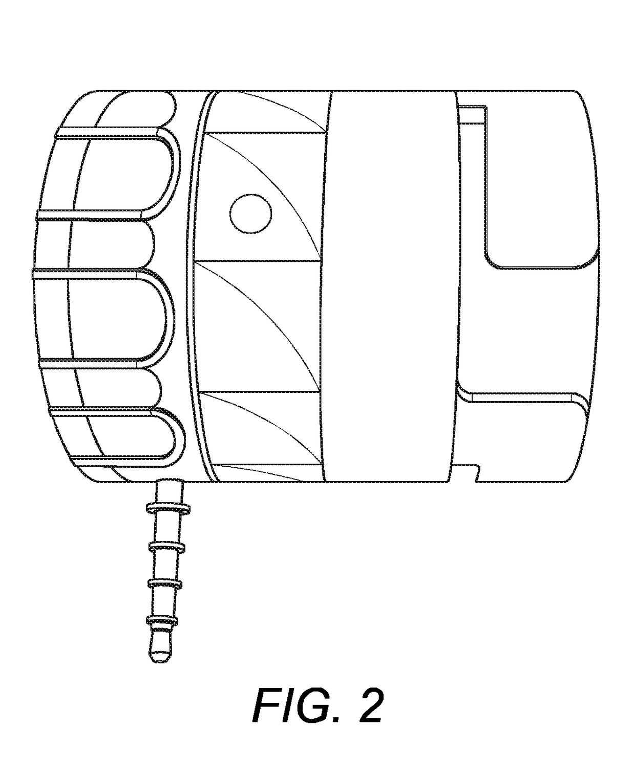
[0076]In these alternative embodiments the spirometer [500], [600] of the invention for measuring throughput air flow shown in FIGS. 4 to 14 features an inlet deflector [602] and an outlet deflector [603] (shown only in FIG. 14 for the third embodiment). Both deflectors [602, 603] have curved spokes and are configured to cause an input airflow to rotate. In other embodiments only one or more than two deflectors may be provided.
[0077]Located between the aforementioned inlet 602 and outlet 603 deflectors is a rotor [504, 604] comprising a vane portion [505, 605] made of opaque plastics material, which is rigidly connected to a shaft portion [506, 606]. The rotor [504, 604] is arranged to be caused to rotate responsive to the rotating air flow. The rotor [504, 604] is arranged so that the end portions of the shaft portion [506, 606] are pivotably mounted in respective sockets [607, 608] (see FIG. 14, for the third embodiment only) defined at the radial centre of the deflectors [602, 60...
first embodiment
[0083]In the first embodiment, shown in FIG. 5, the cylindrical wall of the spirometer has a single window [520] and multiple, in this case two, photodiodes [521D1, 521D2] arranged to be spaced at angles to each other relative to the window [520]. The photocurrent produced by the photodiodes [521D1, 521D2] as the rotor [504] rotates is staggered in time, the ordering of which reveals the direction of rotation. For example, when the rotor [504] rotates in an anti-clockwise direction during inhalation, the photocurrent produced by photodiode 521D1 peaks first, followed shortly by the photocurrent produced by the other photodiode 521 D2, after which they both are not illuminated and so do not produce any photocurrent. On exhalation, the ordering of the peaks is reversed as the rotor [504] then rotates in the clockwise direction.
[0084]In the second embodiment, shown in FIG. 6, the cylindrical wall of the spirometer 600 comprises a single window [620] and a single photodiode [621D]. In o...
second embodiment
[0088]In the second embodiment, as shown in the top panel of FIG. 10 the raw electrical signal produced in the electrical network due to the photocurrent produced by the photodiode exhibits a sawtooth peak twice per complete rotation of the vane portion [604]. Due to the bias voltage applied by the smartphone's microphone circuit the raw signal shown at FIG. 10 is above and below a zero level. The sawtooth pattern of the circuit can be detected in an output signal, which when measured over time, allows a rotation rate of the rotor [605] to be determined for example by applying a Discrete Fourier Transform (DFT) or Fast Fourier Transform (FFT).
[0089]To circumvent activation of the smartphone's low resistance direct contact responses (below 1 k Ohm) when the rotor [605] is caused to rotate in response to the rotating airflow, like in the first embodiment a 1 k Ohm resistor (not shown) is incorporated into the electrical network by placing it in serial connection with the photodiode [6...
PUM
 Abstract
Description
Claims
Application Information
 - R&D Engineer
- R&D Manager
- IP Professional
- Industry Leading Data Capabilities
- Powerful AI technology
- Patent DNA Extraction
Browse by: Latest US Patents, China's latest patents, Technical Efficacy Thesaurus, Application Domain, Technology Topic, Popular Technical Reports.
© 2024 PatSnap. All rights reserved.Legal|Privacy policy|Modern Slavery Act Transparency Statement|Sitemap|About US| Contact US: help@patsnap.com


