Method for controlling the movement of a drive axis of a drive unit

a technology of drive unit and drive axis, which is applied in the direction of electric programme control, program control, instruments, etc., can solve the problems of high computational cost, difficult calculation of movement profiles, and complex structure of the conveying device in the form of a long-stator linear motor, so as to reduce the effort and time for initialization, and reduce the computational effor

Active Publication Date: 2017-08-10
B&R IND AUTOMATION GMBH
View PDF1 Cites 11 Cited by
  • Summary
  • Abstract
  • Description
  • Claims
  • Application Information

AI Technical Summary

Benefits of technology

[0015]According to the invention, it can be ensured that the movement is continued continuously also after activating the smoothing filter at the current movement phase. At the same time, this enables the output of the smoothing filter to be continuous and therefore differentiable, by means of which the repeated time derivative of the highest time derivative in the movement phase, e.g. the jerk or the change in the jerk with respect to time, is limited. In this way, the smoothing filter can be activated without negative effects at any time, in particular also during a movement of the drive axis, and not only at the beginning of the movement.
[0016]Preferably, a constant function is assumed for the highest time derivative of the setpoint for the previo...

Problems solved by technology

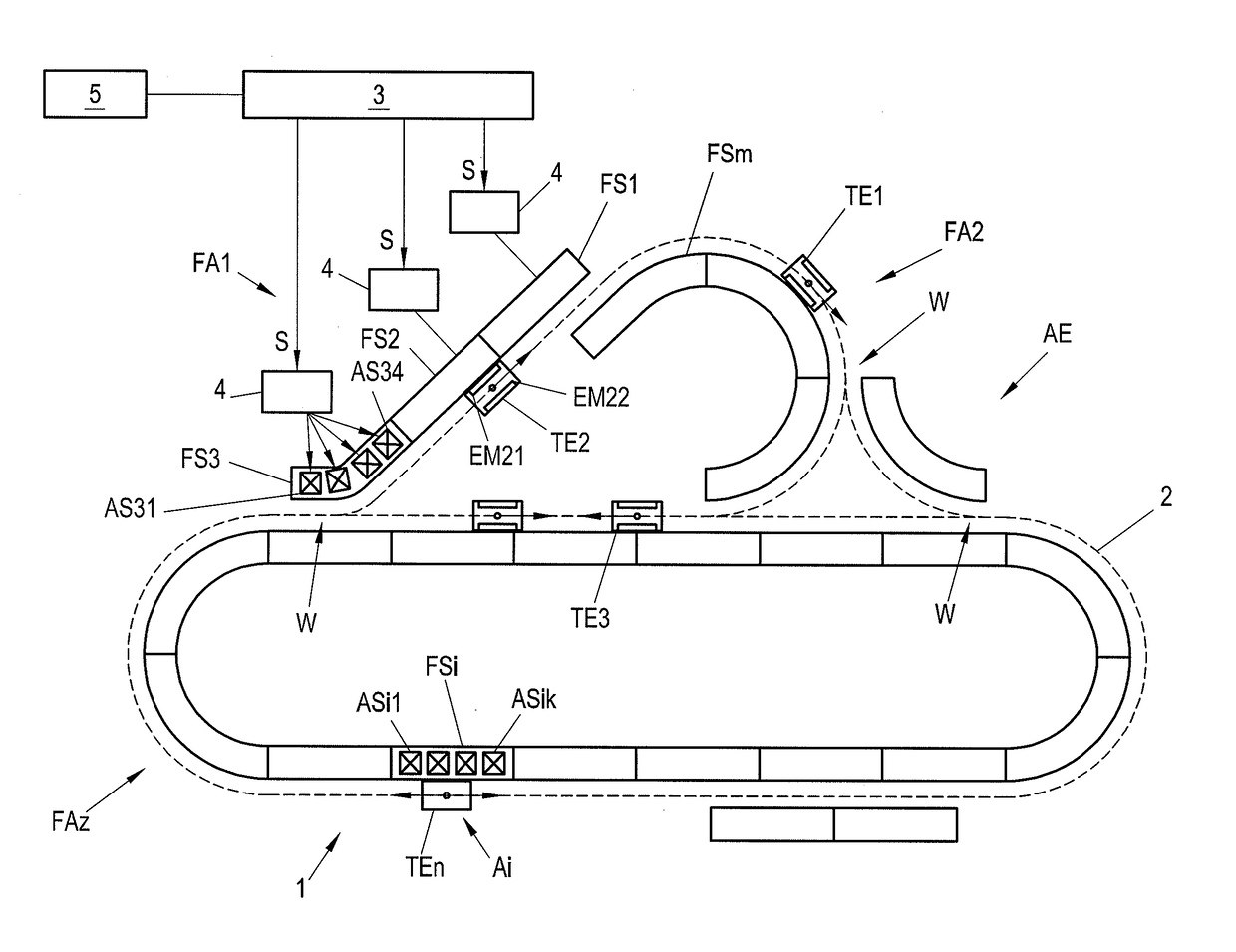
A conveyor device in the form of a long-stator linear motor can become quite complex with a plurality of transport sections which can be connected to one another by means of track switches.
Such a conveyor device therefore imposes high demands on the control of the movement of the individual transport units.
However, the generation of such movement profiles is very calculation-intensive.
Particularly in the case of applications such as a conveyor device in the form of a long-stator linear motor where there is a multiplicity of transport units to be moved, the limits of available computational power are quickly reached.
However, such low-pass filters are likewise calculation-intensive.
For a conveyor device having a multiplicity of t...

Method used


Image

  • Method for controlling the movement of a drive axis of a drive unit
  • Method for controlling the movement of a drive axis of a drive unit
  • Method for controlling the movement of a drive axis of a drive unit

Examples


Embodiment Construction

[0014]Embodiments of the present invention are directed to a method which enables, with little computational effort, the movement of a drive axis of a drive unit to be controlled by specifying setpoints, wherein a smoothing filter in the form of a averaging filter can also be activated during the movement of the drive axis while maintaining the specified kinematic limits, in particular the jerk or the change in the jerk with respect to time.

[0015]According to the invention, it can be ensured that the movement is continued continuously also after activating the smoothing filter at the current movement phase. At the same time, this enables the output of the smoothing filter to be continuous and therefore differentiable, by means of which the repeated time derivative of the highest time derivative in the movement phase, e.g. the jerk or the change in the jerk with respect to time, is limited. In this way, the smoothing filter can be activated without negative effects at any time, in pa...


PUM


Abstract

To be able to activate a smoothing filter for a setpoint, with which the movement of a drive axis (A, Ai) of a drive unit (AE) can also be controlled during the movement without a negative effect on the movement, it is provided that the smoothing filter (10) is initialized with a setpoint profile (Sinit) so that a current movement phase ((S0, {dot over (S)}0, . . . , S0(x))) is continued continuously and the repeated time derivative (S(x+1)) of the highest time derivative (S(x)) of the setpoint (S(t), S(k)) is limited.

Description

CROSS-REFERENCE TO RELATED APPLICATIONS[0001]The present application claims priority under 35 U.S.C. §119(a) of Austria Patent Application No. A50073 / 2016 filed Feb. 5, 2016, the disclosure of which is expressly incorporated by reference herein in its entirety.BACKGROUND OF THE INVENTION[0002]1. Field of the Invention[0003]The present invention relates to a method for controlling the movement of a drive axis of a drive unit, wherein the movement of the drive axis is controlled in a cycle step by specifying a setpoint of the movement, by means of which there results a movement phase of the movement of the drive axis, wherein a smoothing filter in the form of an averaging filter calculates the new setpoint as the mean value of the previous setpoints at a filter time in the past.[0004]2. Discussion of Background Information[0005]Long-stator linear motors are often used as flexible conveying devices in manufacturing lines, processing lines, assembly lines and similar systems. As is know...

Claims


Application Information

Patent Timeline
IPC IPC(8): H02P25/06B65G43/00
CPCH02P25/06B65G2203/047B65G43/00G05B19/41G05B19/416G05B2219/41217G05B2219/41222G05B7/02
Inventor HUBER, STEFANHERZOG, HELMUT
Owner B&R IND AUTOMATION GMBH
Why Eureka
Try Eureka