
Connecting device and method for connecting

Active Publication Date: 2017-08-10
VEGA GRIESHABER GMBH & CO
View PDF3 Cites 4 Cited by
  • Summary
  • Abstract
  • Description
  • Claims
  • Application Information

AI Technical Summary

Benefits of technology

The invention provides a circuit that can safely and efficiently handle sudden increases in current consumption, such as in a computer chip or display. The circuit uses a capacitor to buffer and provide the required current without the need for a separate power source. This makes the circuit safer and more efficient than traditional power supplies. The circuit also has a feature that allows for the direct connection of components with low current consumption, such as a display or keypad, without causing a large voltage drop. In addition, the circuit can also handle the temporary use of a large current spike without overcharging the circuit, which can lead to a detrimental effect on the overall performance of the circuit.

Problems solved by technology

The current consumption of electronic devices and apparatus in intrinsically safe current circuits is often limited by resistors in the feed line in order to prevent an ignitable spark.
However, a resistor in an electrical line also limits the maximum possible current consumption of connected equipment.
In particular, the mean current consumption and, in particular, the peak current consumption can be limited by resistors in the supply lines.
However, components which are configured for a small current consumption are complex to manufacture and are therefore associated with corresponding costs.

Method used


Image

  • Connecting device and method for connecting
  • Connecting device and method for connecting
  • Connecting device and method for connecting

Examples


Embodiment Construction

[0045]The illustrations in the figures are schematic and not to scale. In the following description of FIGS. 1 to 8, the same reference numbers are used for the same or corresponding elements.

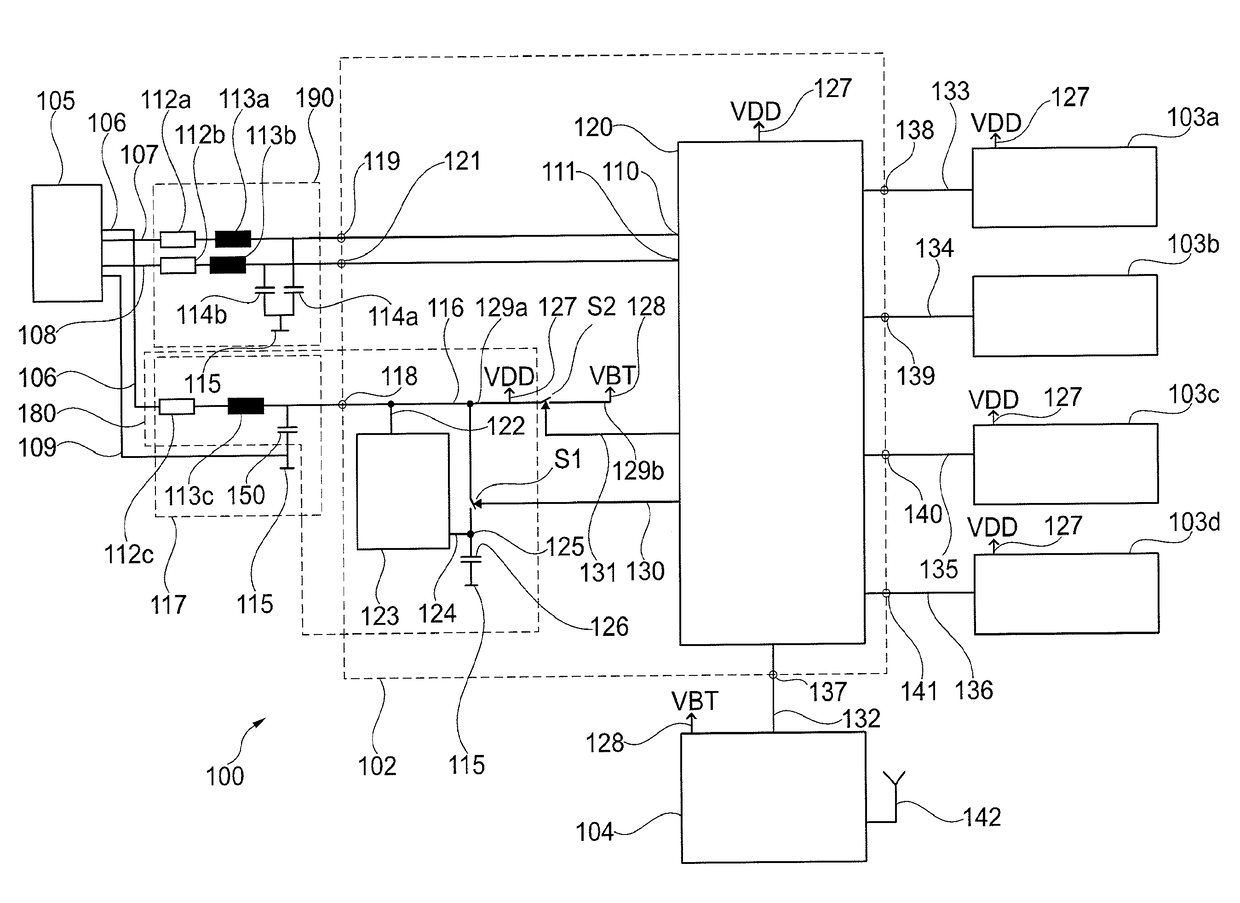
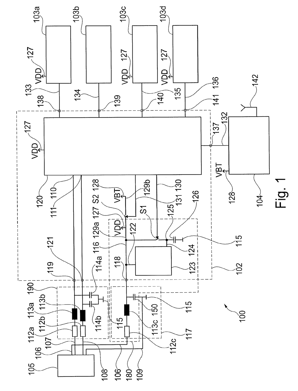
[0046]FIG. 1 is a circuit arrangement 100 comprising an input current circuit 117, the connecting device 102 and a multiplicity of consumers with a small current requirement 103a, 103b, 103c, 103d as well as a consumer with a large current requirement 104.

[0047]No current supply is shown in FIG. 1. A current supply can be associated with the input current circuit 117. However, FIG. 1 shows the contact surface 105 with four current connections 106, 107, 108, 109. A current supply can be connected to the contact surface 105 which can form an external connection, for example, by means of sliding contacts. The contact surface can be configured as a physical I2C bus or I2C bus (inter-integrated circuit) and connected via sliding contacts to the current supply and / or further data lines which can be a...


PUM


Abstract

A connecting device is provided, including a control apparatus, an energy storage apparatus, an input connection, and an output connection, the input connection being connected to the energy storage apparatus by means of a charging apparatus, the charging apparatus being configured for controlled charging of the energy storage apparatus, the control apparatus being configured, after reaching a preset charge state of the energy storage apparatus, to connect the energy storage apparatus to the input connection; and the control apparatus also being configured, during and / or following connection of the energy storage apparatus to the input connection, to connect the input connection to the output connection.

Description

FIELD OF THE INVENTION[0001]The present invention relates to the technical field of measurement technology, in particular, fill level and limit level measurement technology and flow measurement technology. The invention relates to a connecting device, to a field device, to a method for connecting an output connection to an input connection and to a computer-readable storage medium.TECHNICAL BACKGROUND OF THE INVENTION[0002]The current consumption of electronic devices and apparatus in intrinsically safe current circuits is often limited by resistors in the feed line in order to prevent an ignitable spark. The prevention of ignitable sparks can help to prevent explosions.[0003]However, a resistor in an electrical line also limits the maximum possible current consumption of connected equipment. In particular, the mean current consumption and, in particular, the peak current consumption can be limited by resistors in the supply lines. Limiting the current consumption also has the resul...

Claims


Application Information

Patent Timeline
IPC IPC(8): H02J9/06
CPCG01F15/00H02J9/061G01F15/063G01F23/00
Inventor ALLGAIER, VOLKERSTAIGER, HOLGERMUELLER, TOBIAS
Owner VEGA GRIESHABER GMBH & CO
Learn More