Wireless monitoring system

Inactive Publication Date: 2017-08-03
COLD CHAIN PARTNERS
View PDF6 Cites 32 Cited by
  • Summary
  • Abstract
  • Description
  • Claims
  • Application Information

AI Technical Summary

Benefits of technology

The patent describes a technology that allows a single smart monitoring device to be used to extend the shelf-life of products, improve food safety, and reduce energy consumption. This device can be a sensor or a reader tag, and it can communicate with other tags using RF, BLE, or WiFi. The device can also be controlled by a mobile app and can transmit data to the cloud or other systems securely. The technology is cost-effective and efficient in reducing waste and food safety risks.

Problems solved by technology

The quality and safety of perishable food products can be significantly impacted by adverse environmental conditions.
Food wastage has severe negative environmental impacts because of the loss of energy, biodiversity, green-house gases, water, soil and other resources embedded in the food that no one consumes.
Studies indicate that globally over 260 million tonnes of food is lost due to temperature abuse.
In the US, this is estimated to cost $50 billion annually.
With the demand and supply of fresh perishable foods increasing, the volume of food wastage, the requirement for energy to operate refrigeration systems and the risk of compromised food safety is also increasing.
This costs the US economy $152 billion annually.
Whilst a variety of monitoring systems are commercially available, the level of adoption by the food industry remains low, primarily due to the high infrastructure cost of these systems.
Manual monitoring processes have many points of failure and provide limited opportunities for pro-active management.
Temperature records are often missed or incorrectly logged, and there are no alerts or notifications when temperatures breach tolerances.
Nor does it assist in improving business efficiencies that result from better management of climate-controlled assets such as cool stores, freezers, merchandising cabinets etc.
Since most sectors within the food industry consider this approach to be expensive and complex, adoption rates are low.

Method used


Image

  • Wireless monitoring system
  • Wireless monitoring system
  • Wireless monitoring system

Examples


Embodiment Construction

[0040]A preferred embodiment of the invention will now be described with reference to the drawings in which:

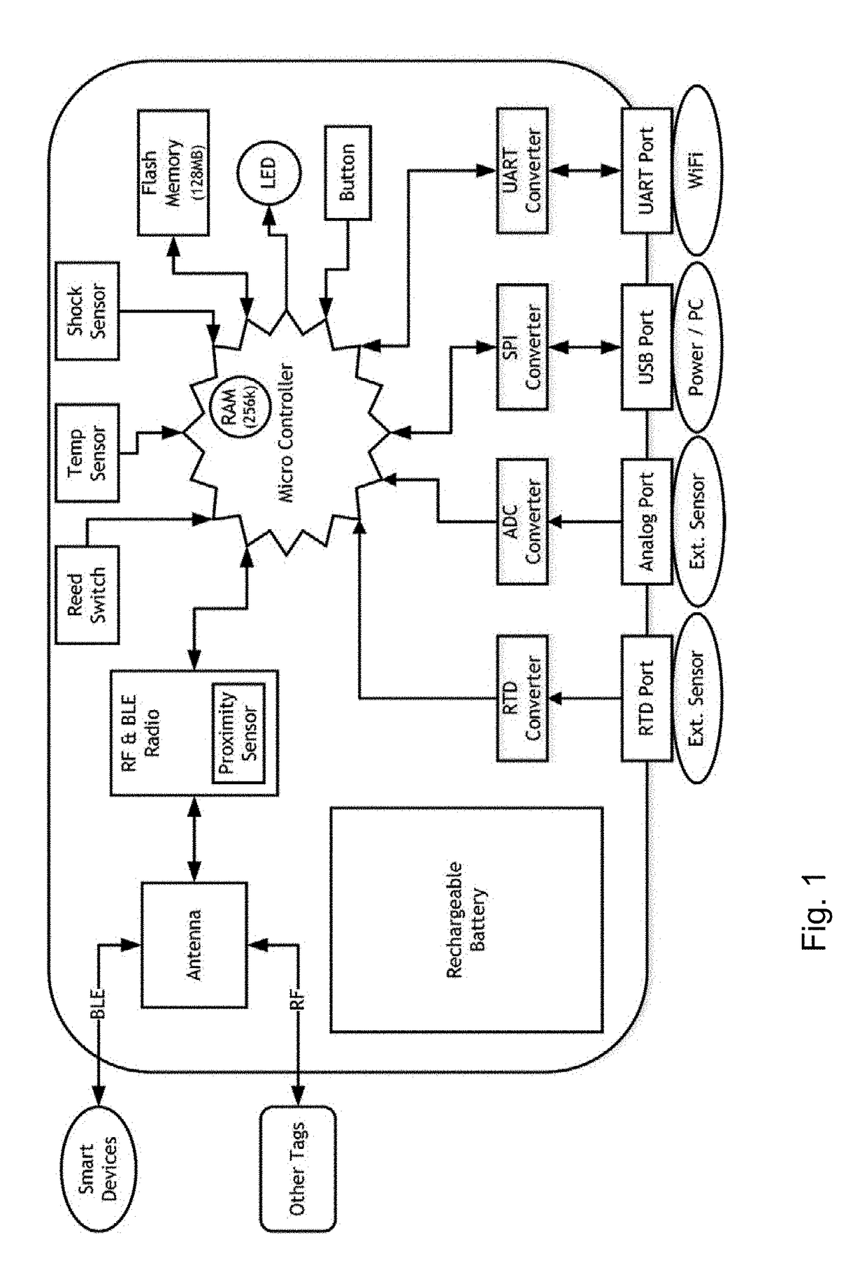
[0041]FIG. 1 is a diagram of the primary hardware components of the Smart Tag embodiment of this invention;

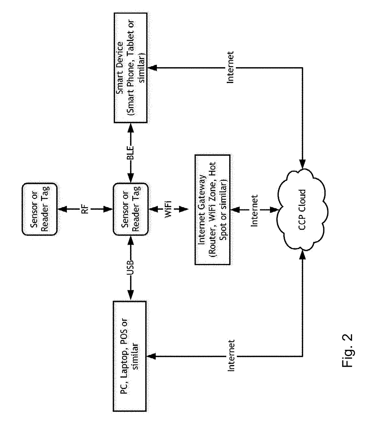
[0042]FIG. 2 is a diagram of the four alternative methods of communication deployed by the Smart Tag embodiment of this invention;

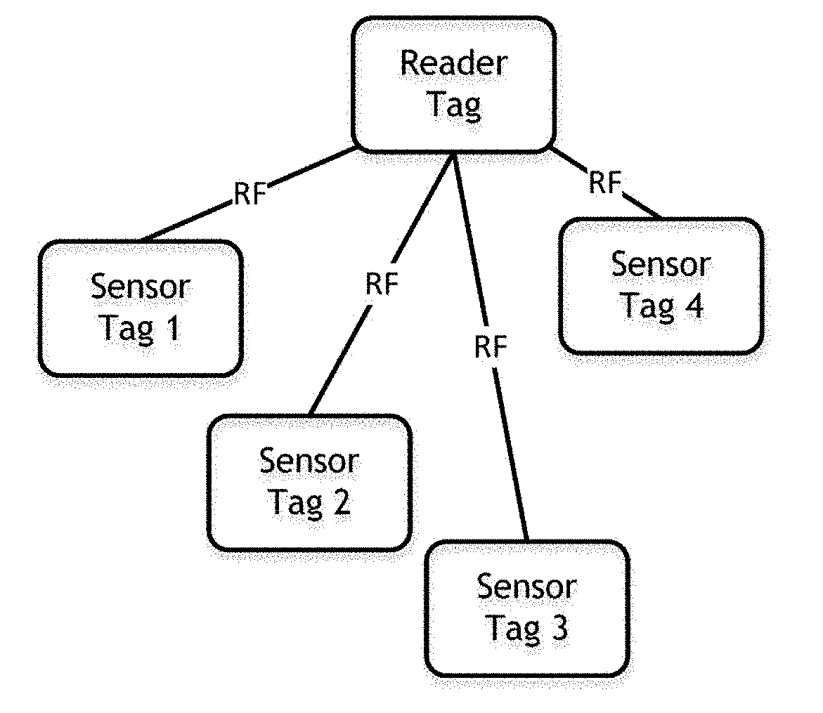
[0043]FIG. 3 depicts each of the major states in which a tag may be configured including:

[0044]FIG. 3a depicts tags in the Sensor (RF Star) Mode

[0045]FIG. 3b depicts tags in the Sensor (RF Mesh) Mode

[0046]FIG. 3c depicts tags in the Sensor (Transitional BLE) Mode

[0047]FIG. 3d depicts tags in the Sensor (Static BLE) Mode

[0048]FIG. 3e depicts tags in the Sensor (WiFi) Mode

[0049]FIG. 3f depicts tags in the Reader (WiFi) Mode

[0050]FIG. 3g depicts tags in the Reader (USB) Mode

[0051]FIG. 3h depicts tags in the Reader (BLE) Mode

[0052]FIG. 3i depicts tags in the Shipment Mode

[0053]FIG. 3j depicts tags in the Shipment (RF Mesh) Mode

[0054]FIG. 4 is an ov...


PUM


Abstract

A system which creates a wireless monitoring network of programmed and computing devices for the capture and transmission of real-time monitoring data. The system uses programmed devices that incorporate at least one sensor, a micro-controller, a data store, transmitters and receivers for multiple wireless communication methods and data input and output ports. The micro-controller may be programmed to operate the programmed device as a collector and transmitter of data from sensors in the programmed device or from other sensors connected to its input port, or as a reader and transmitter of data from other programmed devices. When a computing device is connected to a programmed device via USB, WiFi or Bluetooth (LE), the programmed device acts as a data reader providing monitoring data to the computing device. The system optimizes communications and power usage to maximize network sustainability and performance by managing alternative functional states with finite state machine firmware.

Description

[0001]This invention relates to wireless monitoring systems and in particular the management of perishable goods in a supply chain including monitoring the environment of goods in transit and storage to manage the delivery and sale of goods before the expiry of the predicted shelf life.BACKGROUND TO THE INVENTION[0002]The need for monitoring and interpretation of product and environmental conditions has burgeoned in recent years as consumers and regulators continue to demand ever-increasing quality, reliability and safety of products. This applies to a multitude of diverse products and services from food to pharmaceutical supplies and from evaporative cooling to computing systems.[0003]The quality and safety of perishable food products can be significantly impacted by adverse environmental conditions. In fact their quality, longevity (shelf-life) and safety is substantially influenced by the temperature at which they are held at all points along the supply chain from production to c...

Claims


Application Information

Patent Timeline
IPC IPC(8): G06Q10/08H04Q9/00
CPCG06Q10/087H04Q2209/40G06Q10/0832H04Q9/00G06Q10/08H04L67/125H04L67/04H04L67/12H04L67/10H04W4/38H04W4/80H04L67/566
Inventor WHITE, MICHAELRAO, KARTHEEK MUNIGOTI SHANKAR
Owner COLD CHAIN PARTNERS
Why Eureka
Try Eureka