
Method And Device For Determining Absolute Speed Of A Rail Vehicle

a technology for absolute speed and rail vehicles, applied in railway signalling and safety, devices using time traversed, instruments, etc., can solve problems such as inaccurate speed determination, and achieve the effect of improving the level of accuracy

Inactive Publication Date: 2017-07-27
SIEMENS MOBILITY AUSTRIA GMBH
View PDF4 Cites 5 Cited by
  • Summary
  • Abstract
  • Description
  • Claims
  • Application Information

AI Technical Summary

Benefits of technology

The invention is a device and method for accurately measuring the speed of a rail vehicle by measuring the time it takes for a wheel to pass over the rail. This is done by analyzing the vibration excitation experienced by the wheel during movement. By calculating the time offset between similar signals from different wheels, the speed of the vehicle can be accurately determined. This technology can be used to improve the accuracy of rail vehicle speed monitoring.

Problems solved by technology

In this conventional method, that the wheel circumference is not a fixed quantity is not taken into account, but changes during the operating life due to wear or profiling.
Slippage between the rail and the wheel is also not taken into account, further falsifying the result.
Overall, the result of the speed as determined is therefore inaccurate.

Method used


Image

  • Method And Device For Determining Absolute Speed Of A Rail Vehicle
  • Method And Device For Determining Absolute Speed Of A Rail Vehicle
  • Method And Device For Determining Absolute Speed Of A Rail Vehicle

Examples


Embodiment Construction

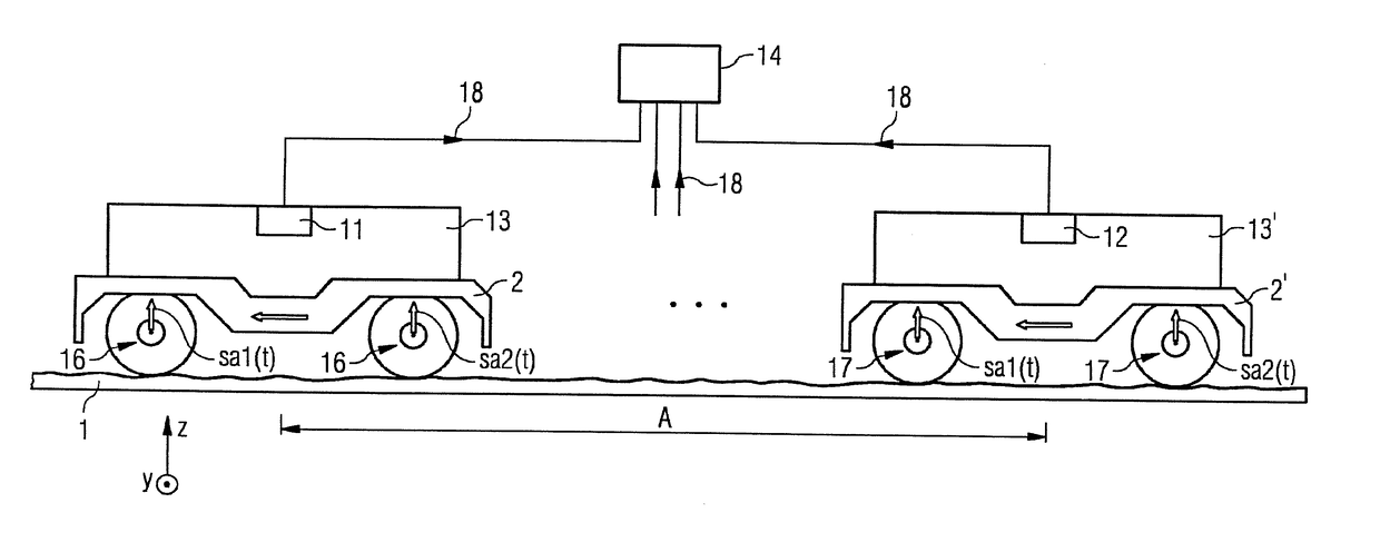
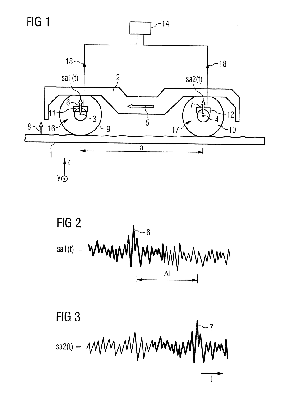
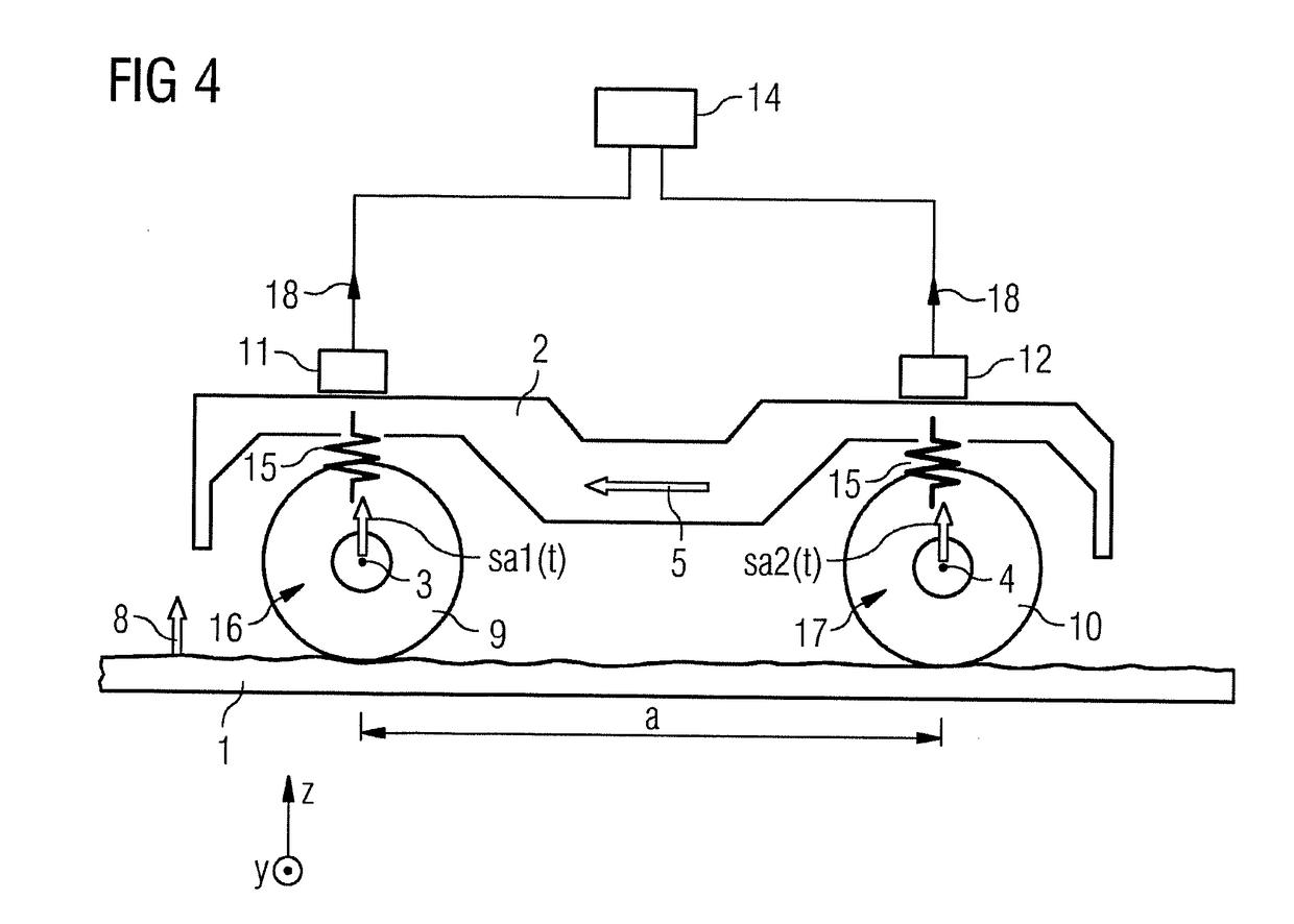
[0032]FIG. 1 shows, in a simplified representation, a wheel truck 2 of a rail vehicle (not shown in detail). Wheels 9, 10 are arranged in pairs on a wheelset 16 positioned in front in the direction of travel and on a following wheelset 17. The wheelsets have an axle spacing “a” from one another. As shown in exaggerated form in FIG. 1, the running surface of the rail 1 is uneven. In the view shown in FIG. 1, the direction of travel is from right to left. If, therefore, the front wheel 9 travels over an unevenness, the following wheel follows it in a temporally offset manner. The unevennesses causes vibration excitations that are evaluated by measuring technology. As FIG. 1 indicates, a sensor device is associated with each axlebox: the sensor device 11 with the front axle, the sensor device 12 with the rear axle. These sensor devices 11, 12 can represent different physical parameters according to embodiment, depending on direction, for example: displacement, speed, acceleration or va...


PUM


Abstract

A method for determining absolute speed of a rail vehicle including onboard sensor devices and a signal processor, wherein the method includes the steps of detecting irregularities in the rail respectively on one front wheel set via a first sensor device and at least on a subsequent wheel set via another sensor device, and transmitting the sensor signals produced by the sensor devices to a signal processor configured to determine the absolute speed by analyzing the supplied sensor signals, where an estimation of the transfer function between a sensor is used, and where an FIR filter can, in this case, optimally reproduce the signal of one sensor via the signal of the other sensor in which the smallest square of the error is formed such that the time offset between both signals can be determined, from which the speed can be determined at a known distance of the sensor.

Description

CROSS-REFERENCE TO RELATED APPLICATIONS[0001]This is a U.S. national stage of application No. PCT / EP2015 / 064320 filed 25 Jun. 2015.BACKGROUND OF THE INVENTION[0002]1. Field of the Invention[0003]The invention relates to a device and a method for determining the absolute speed of a rail vehicle, where sensor devices and a signal processing device are provided on board the rail vehicle.[0004]2. Description of the Related Art[0005]In rail vehicles nowadays the speed is normally determined by measuring the wheel rotation rate with a magnet wheel and a magnet wheel sensor, where the sensor signal is fed to a signal processing device, and multiplied at this location by the wheel circumference.[0006]In this conventional method, that the wheel circumference is not a fixed quantity is not taken into account, but changes during the operating life due to wear or profiling. Slippage between the rail and the wheel is also not taken into account, further falsifying the result. Overall, the result...

Claims


Application Information

Patent Timeline
IPC IPC(8): G01P3/80G01P15/16G01P3/50
CPCG01P3/803G01P15/16G01P3/50B61L25/021G01P3/64G01P15/00
Inventor SALZGEBER, GERARD
Owner SIEMENS MOBILITY AUSTRIA GMBH
Learn More