
Radio Frequency System and Method for Monitoring Engine-Out Exhaust Constituents

a radio frequency system and exhaust constituent technology, applied in the direction of transmission monitoring, separation processes, instruments, etc., can solve the problems of not functioning appropriately by definition, unable to dynamically capture utilizing predictive models, and changes that occur to the engine, so as to reduce the measurement response time

Active Publication Date: 2017-07-27
CTS CORP ELKHART
View PDF1 Cites 30 Cited by
  • Summary
  • Abstract
  • Description
  • Claims
  • Application Information

AI Technical Summary

Benefits of technology

The patent describes a method to improve the quality of radio frequency signals by adjusting the power transmitted to the sensors and by sampling the signals in specific narrow ranges to decrease measurement response time. The technical effect of this invention is to enhance the accuracy and speed of radio frequency signal analysis.

Problems solved by technology

These indirect methods have suffered from a number of shortcomings including for example the fact that these models are typically developed and calibrated given a specific set of boundary conditions or system inputs including, but not limited to, engine characteristics and operating parameters, fuel and lubricant type, aging factors, safety margins, and the like that require tuning to a specific set of input conditions which may not be universally applicable to all engines or systems and thus require some customization for each end-use application.
Virtual sensors that rely on these known set of operating conditions to accurately estimate engine emissions such as, for example, the composition, amount, rate, or concentration of the emissions in the exhaust have not by definition functioned appropriately over conditions or abnormal operation outside the capabilities of the predictive models.
Also, changes that occur to the engine as the engine ages and components wear or break down, or changes that occur to the catalysts as the catalysts age or become poisoned, cannot be dynamically captured utilizing predictive models.
Generally, safety factors or deterioration factors are used to compensate for these changes resulting in a trade-off in overall performance that is generally too conservative when the engine is new in order to satisfy the system useful life requirements.
The predictive model approach also suffers from the lack of any feedback mechanism to directly determine whether the system performance has degraded beyond the assumed safety margins.
Moreover, the development, calibration, and tuning of the predictive models for a specific engine and application is time consuming and costly.
In the case of particulate filters, pressure or differential pressure sensors have also been used but they suffer from a lack of resolution and response.
In particular, exhaust backpressure or measurements of the particulate filter differential pressure are impacted by a wide range of noise factors including exhaust flow rate, temperature, particulate matter distribution, filter characteristics (hysteresis effects), and the like.
Pressure measurements also do not provide a direct measure of particulate matter in the exhaust and lack the resolution to detect particulate matter build-up on the filter necessary to estimate engine-out PM emissions rates.
Furthermore, pressure measurements are not reliable overall operating conditions, such as low flow (idle), with the engine off, during regeneration, or over transient events for example.
This approach, therefore, does not provide a continuous measurement.
This signal averaging or filtering significantly increases the sensor's response time, making it unsuitable for any type of meaningful feedback control applications.
Soot sensors however have a low measurement range thus resulting in a sensor that is quickly overwhelmed by the high levels of engine-out soot emissions.
Also, soot sensors are designed to measure very low concentrations of soot in the exhaust gas stream (after the particulate filter) and are not suitable for measuring high levels of engine-out particulate matter emissions.
Further, soot sensors only monitor a portion of the exhaust gas flow, and therefore do not provide a direct measurement of the total soot levels in the exhaust gas, but only the levels in the exhaust gas in close proximity to the sensor (or flowing through the sensor housing).
These sensors however do not provide a continuous monitor but rather cycle from a measuring state to a regeneration state.
The sensors also require condensate protection, which does not allow them to operate during certain conditions, such as cold start for example when they may be needed most.
Soot sensors also suffer from poor durability, the accumulation of contaminants (such as ash), as well as thermal shock (water in the exhaust or condensation), which limits the sensor life and accuracy over its useful life.
Due to the intermittent nature of the sensor operation which includes regeneration event followed by time period required for sufficient accumulation to generate a measurable response, these sensors also do not provide a continuous measurement.
These types of sensing elements are fragile and may suffer from a number of failure modes in the field.
In particular, it is well known that many gas sensors suffer from cross-sensitivities to other exhaust gas constituents, errors due to variations in the local gas velocity or flow rate near the sensing element, and temperature-related effects, among others.
These sensors may also become poisoned due to contaminants in fuels, lubricants, or the environment.
In another example, the sensor may become damaged when used in certain conditions.
Many of these sensors also require significant energy input, such as from heaters, to enable their operation, and may not function over all operating conditions, such as changes in the air-fuel ratio in one example, or cold start conditions in another.

Method used


Image

  • Radio Frequency System and Method for Monitoring Engine-Out Exhaust Constituents
  • Radio Frequency System and Method for Monitoring Engine-Out Exhaust Constituents
  • Radio Frequency System and Method for Monitoring Engine-Out Exhaust Constituents

Examples


Embodiment Construction

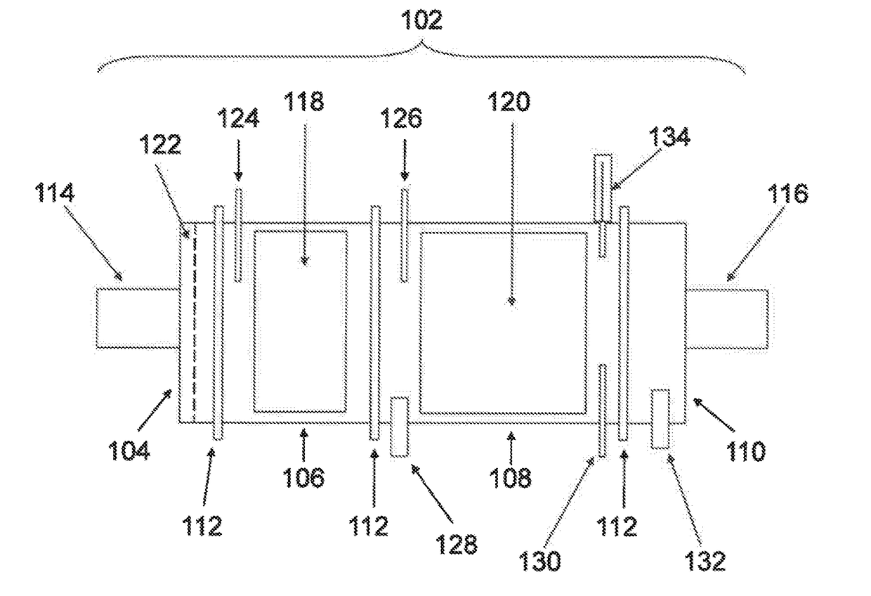
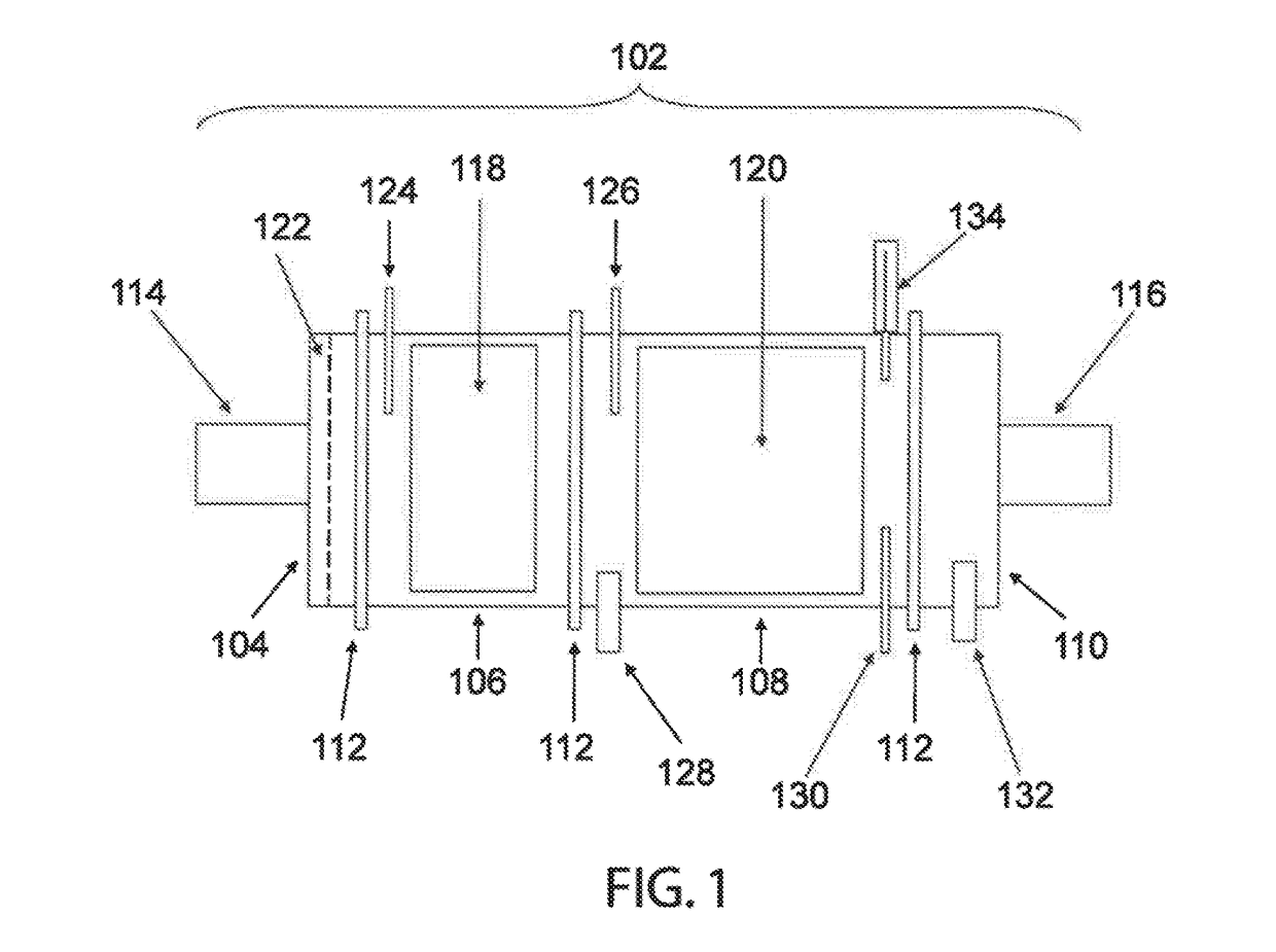
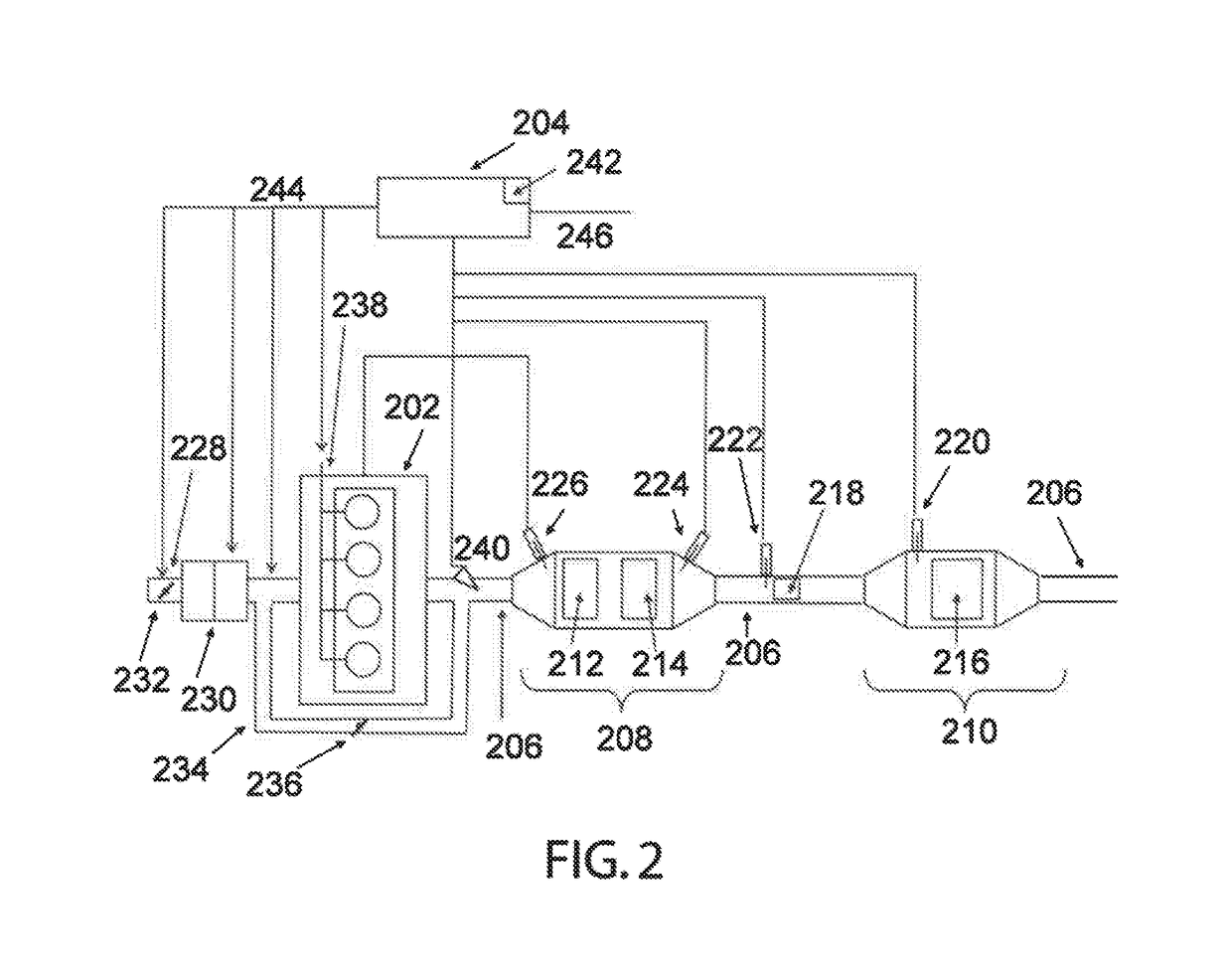
[0047]The invention relates to a radio frequency based system and method for monitoring engine-out exhaust emissions constituents as well as providing feedback control capabilities based on the monitored emissions.

[0048]For the purposes of this disclosure, the term emissions constituent refers to any solid, liquid, or gas phase emissions, whether resulting directly from the upstream process (such as combustion) as in the case of particulate matter constituents, or emission constituents introduced into the exhaust system through the use of additives or dosing, such as hydrocarbon or urea dosing in one example.

[0049]The terms particulate matter (PM) and soot are used interchangeably, and refer to particulate matter emission constituents which may contain carbon, hydrocarbons, sulfates, ash, or other materials. However, the invention is broadly applicable to monitoring the rates of emissions constituents in general, in which case particulate matter may be more broadly defined to includ...


PUM

PropertyMeasurementUnit
radio frequency systemaaaaaaaaaa
radio frequencyaaaaaaaaaa
frequencyaaaaaaaaaa

Abstract

A radio frequency system and method for monitoring an engine-out exhaust emission constituent. The system comprises a housing containing the emission constituent, one or more radio frequency sensors extending into the housing and transmitting and receiving radio frequency signals, and a control unit for controlling the radio frequency signals and monitoring changes in the emission constituent based on changes in one or more parameters of the radio frequency signals. In one embodiment, the control unit measures a rate of change in one or more of the parameters of the radio frequency signals for monitoring a rate of change of the emission constituent including for example the emission rate, accumulation rate, and / or depletion rate of the emission constituent.

Description

CROSS-REFERENCE TO RELATED APPLICATIONS[0001]This patent application claims priority and benefit of the filing date of and is a continuation-in-part of U.S. patent application Ser. No. 14 / 733,525 filed on Jun. 8, 2015 and U.S. patent application Ser. No. 14 / 733,486 filed on Jun. 8, 2015, the disclosure and contents of which are expressly incorporated herein in their entireties by reference.[0002]This patent application also claims priority and benefit of the filing date of U.S. Provisional Patent Application Ser. No. 62 / 320,707 filed on Apr. 11, 2016, the disclosure and contents of which is expressly incorporated herein in its entirety by reference.GOVERNMENT SPONSORSHIP[0003]This invention was made with government support under Award No. IIP 1330313 awarded by the National Science Foundation. The government has certain rights in the invention.FIELD OF THE INVENTION[0004]This invention relates to a radio frequency system and method for monitoring engine exhaust emissions constituent...

Claims


Application Information

Patent Timeline
Patent Type & Authority Applications(United States)
IPC IPC(8): F01N11/00B01D53/94H04B17/18G01N22/04H04B17/309H04W24/08F01N3/20
CPCF01N11/00H04W24/08B01D53/9495F01N3/208F01N2610/148H04B17/309H04B17/18B01D53/9422B01D2255/911G01N22/04F01N3/2066F01N3/021G01N15/00F01N2560/00F01N2560/12F01N2560/14Y02T10/12
Inventor SAPPOK, ALEXANDER G.RAGALLER, PAUL A.BROMBERG, LESLIEHERMAN, ANDREW D.
Owner CTS CORP ELKHART
Learn More