Light emitting module

a technology of light emitting modules and led light sources, which is applied in the direction of semiconductor devices for light sources, lighting and heating apparatus, printed circuit non-printed electric components association, etc., can solve the problems of difficult scaling of led luminaires, inability to achieve general enough light output of led light sources, and inability to achieve general enough light output for most applications, etc., to achieve efficient light distribution and avoid high brightness spots.

Inactive Publication Date: 2017-07-20
SIGNIFY HLDG BV
View PDF5 Cites 7 Cited by
  • Summary
  • Abstract
  • Description
  • Claims
  • Application Information

AI Technical Summary

Benefits of technology

The present invention aims to provide a light emitting module that can be reshaped and has adjustable light intensity without changing the number of LEDs emitting light. The module has flexible LED-carrier or strip with adjustable light exit opening that can be adjusted by flexing or folding the carrier. This allows for efficient light distribution and avoids high brightness spots in the LED luminaire. The module has simple and flexible electrical contacting arrangements via the top and bottom plates with the LED-strip, which enables free positioning of the LED-strip without the need for loose wiring. The flexibility of the LED-strip changes the area of the light exit opening, resulting in changing the intensity of the light emitting module. This eliminates the need for changing the number of LEDs emitting light for changing the light intensity of the module, simplifies the design and manufacturing of the module, and allows for the use of the same type of LED-strip in different lighting applications requiring different light intensities.

Problems solved by technology

The light output of a LED light source is, however, not generally sufficient for most applications, and several LED light sources have to be combined to generate sufficient light levels.
This may, however, be difficult to achieve as a change in the shape of the luminaire may need rescaling and / or cutting of surfaces where the LEDs are mounted.
LED luminaires are not easily scalable in size nor is the number of LED light sources used in the luminaire easy to adjust without having to change the design of the luminaire.

Method used


Image

  • Light emitting module
  • Light emitting module
  • Light emitting module

Examples


Embodiment Construction

[0048]The present invention will now be described more fully hereinafter with reference to the accompanying drawings, in which currently preferred embodiments of the invention are shown. This invention may, however, be embodied in many different forms and should not be construed as limited to the embodiments set forth herein; rather, these embodiments are provided for thoroughness and completeness, and fully convey the scope of the invention to the skilled person.

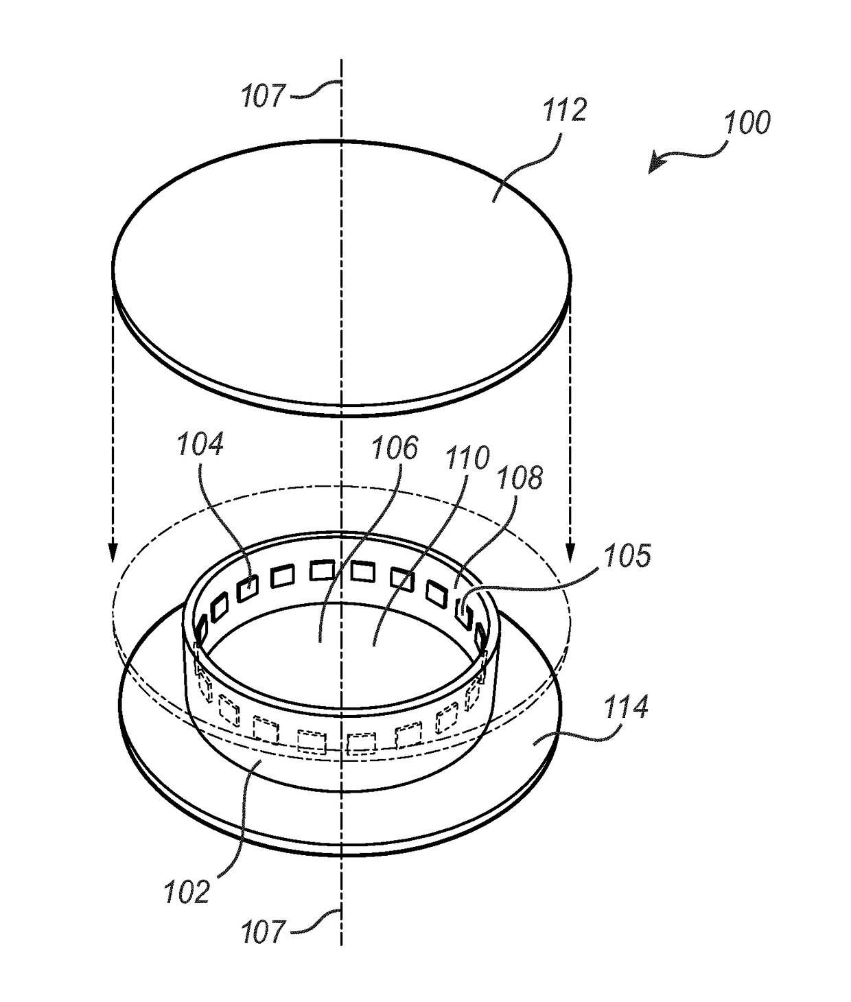
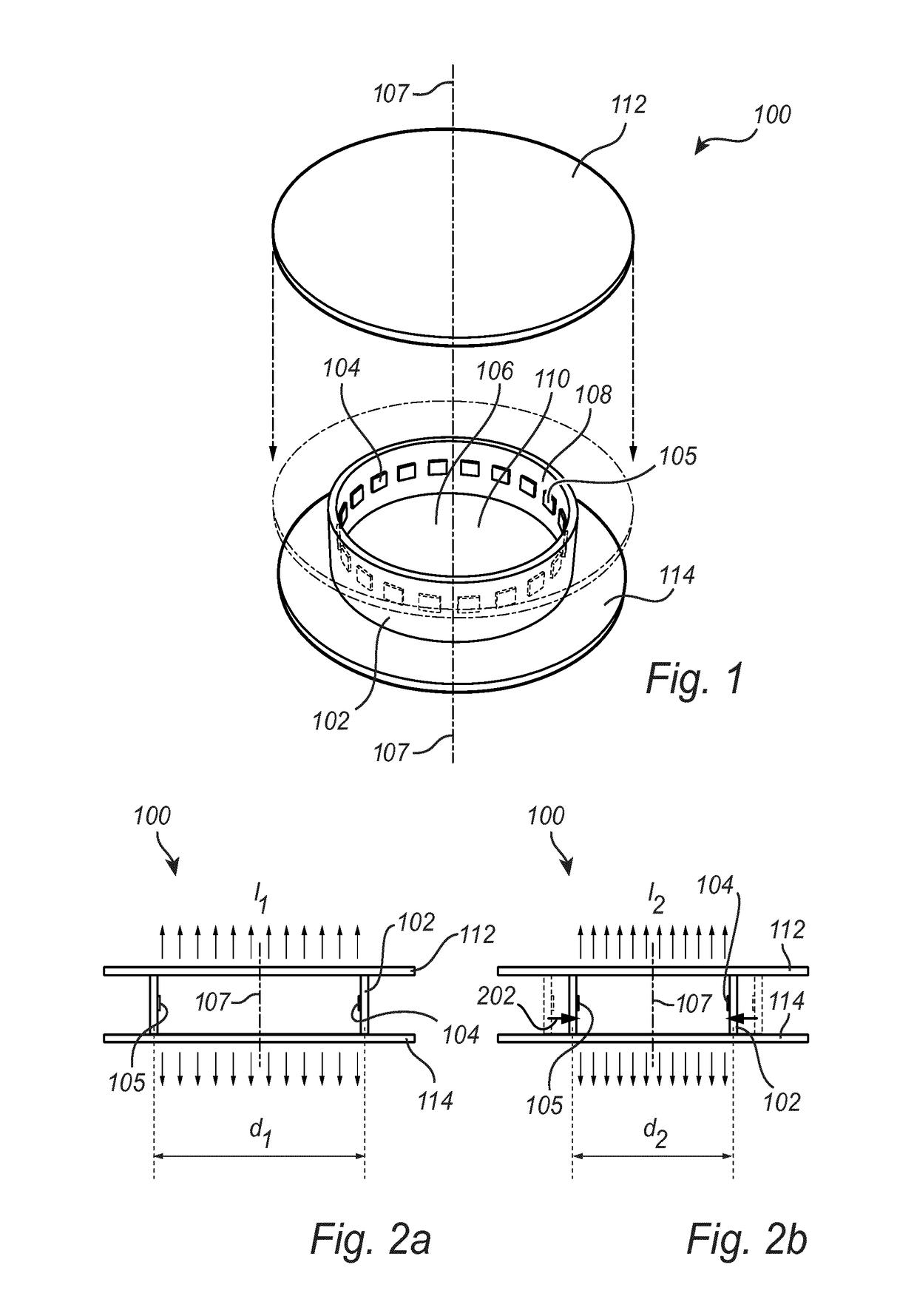
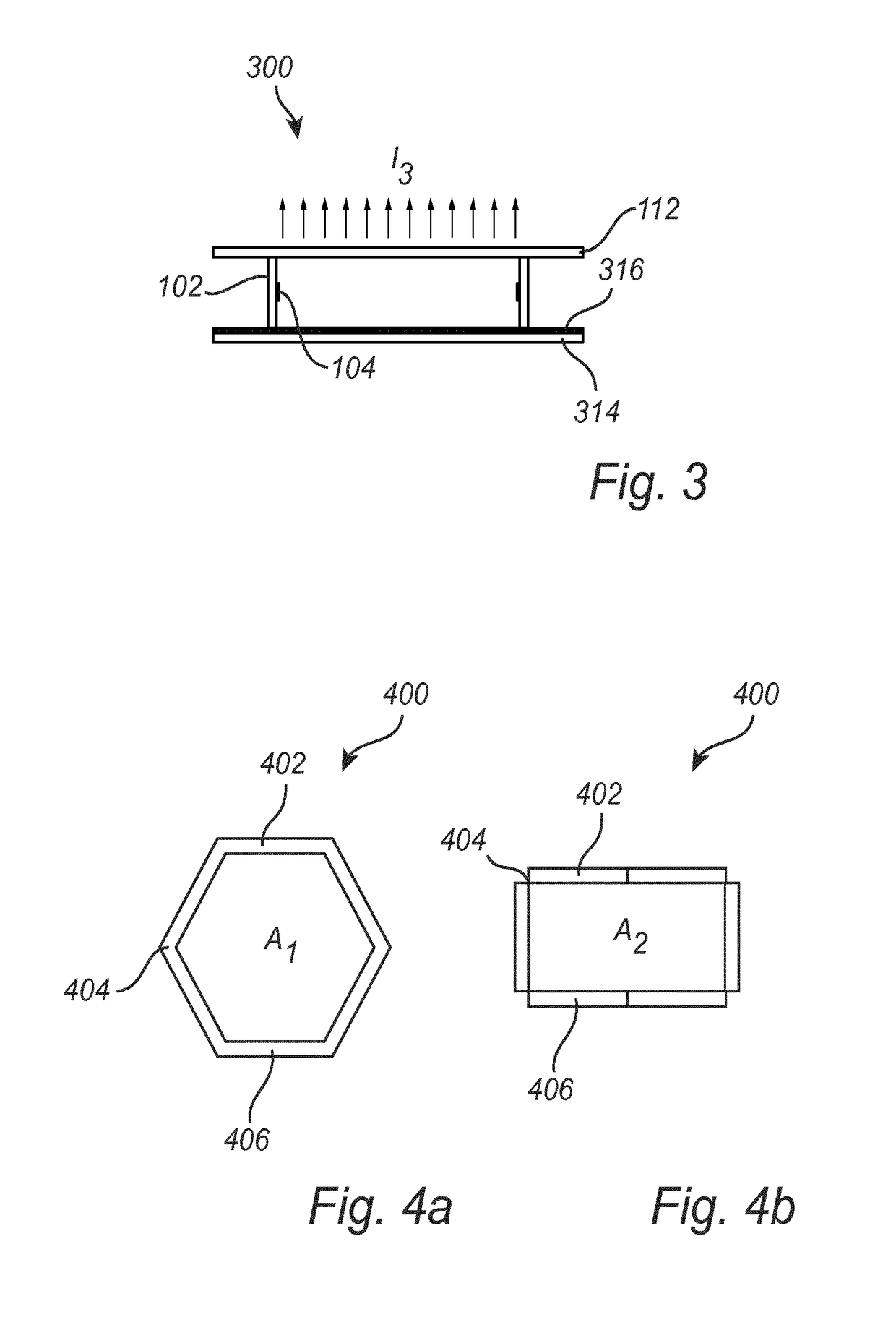
[0049]FIG. 1 illustrates an embodiment of a light emitting module 100 according to the present invention. The light emitting module 100 comprises a closed loop around an axis 107 of a flexible LED-carrier 102, for example a strip, with a plurality of light emitting diodes, LEDs, 104 and a light exit opening 106 with the axis 107 normal to said light exit opening. The LEDs 104 are arranged on an inner surface 108 of the flexible LED-strip 102.

[0050]The flexible LED-carrier 102 is made of a flexible printed circuit board, PCB...


PUM


Abstract

The invention relates to a light emitting module, in particular a light emitting module comprising, a flexible and / or foldable LED-strip (102, 402, 502, 602, 702, 802, 902) comprising at least one light emitting diode (104, 904, 905), the LED-strip (102, 402, 502, 602, 702, 802, 902) forming a light cavity (110, 510, 810, 910), and a light exit opening (106, 506, 806) allowing light to exit the light cavity (110, 510, 810, 910), wherein the at least one light emitting diode (104, 904, 905), faces the light cavity (110, 510, 810, 910), and wherein a shape of the light exit opening (106, 506, 806) is dependent on a flexing and / or folding of the LED-strip (102, 402, 502, 602, 702, 802, 902). The invention also relates to a LED-lamp (1000) and a LED-luminaire (2000) comprising such a light emitting module. A method (3000) for changing the light intensity of a light emitting module is further provided.

Description

FIELD OF THE INVENTION[0001]The invention relates to a light emitting module. The invention also relates to a lamp and a luminaire comprising such a light emitting module. A method for changing the light intensity of a light emitting module is further provided.BACKGROUND OF THE INVENTION[0002]Light emitting diodes (LEDs) are commonly, for practical as well as aesthetical reasons, used in luminaires for providing efficient general lighting and functional light in public spaces, buildings, offices, homes etc. The light output of a LED light source is, however, not generally sufficient for most applications, and several LED light sources have to be combined to generate sufficient light levels.[0003]It is often desirable to change the shape or size of the luminaire as well as its light intensity in order to meet the needs of the lighting situation at hand.[0004]This may, however, be difficult to achieve as a change in the shape of the luminaire may need rescaling and / or cutting of surfa...

Claims


Application Information

Patent Timeline
Patent Type & Authority Applications(United States)
IPC IPC(8): H05K1/18F21K9/233H01L25/075
CPCH05K1/189H01L25/0753F21K9/233F21Y2115/10F21Y2103/33F21Y2107/90H05K2201/10106
Inventor VAN BOMMEL, TIESHIKMET, RIFAT ATA MUSTAFADIJKEN, DURANDUS KORNELIUS
Owner SIGNIFY HLDG BV
Why Eureka
Try Eureka