Front end circuit and communication apparatus
a front-end circuit and communication device technology, applied in electrical devices, multiple-port networks, waveguide-type devices, etc., can solve the problems of increasing the loss of signals to be transmitted/received to/from antennas, narrowing the antenna band, etc., to achieve the effect of further enhancing the isolation between a transmission circuit and a reception circui
- Summary
- Abstract
- Description
- Claims
- Application Information
AI Technical Summary
Benefits of technology
Problems solved by technology
Method used
Image

Examples
first embodiment
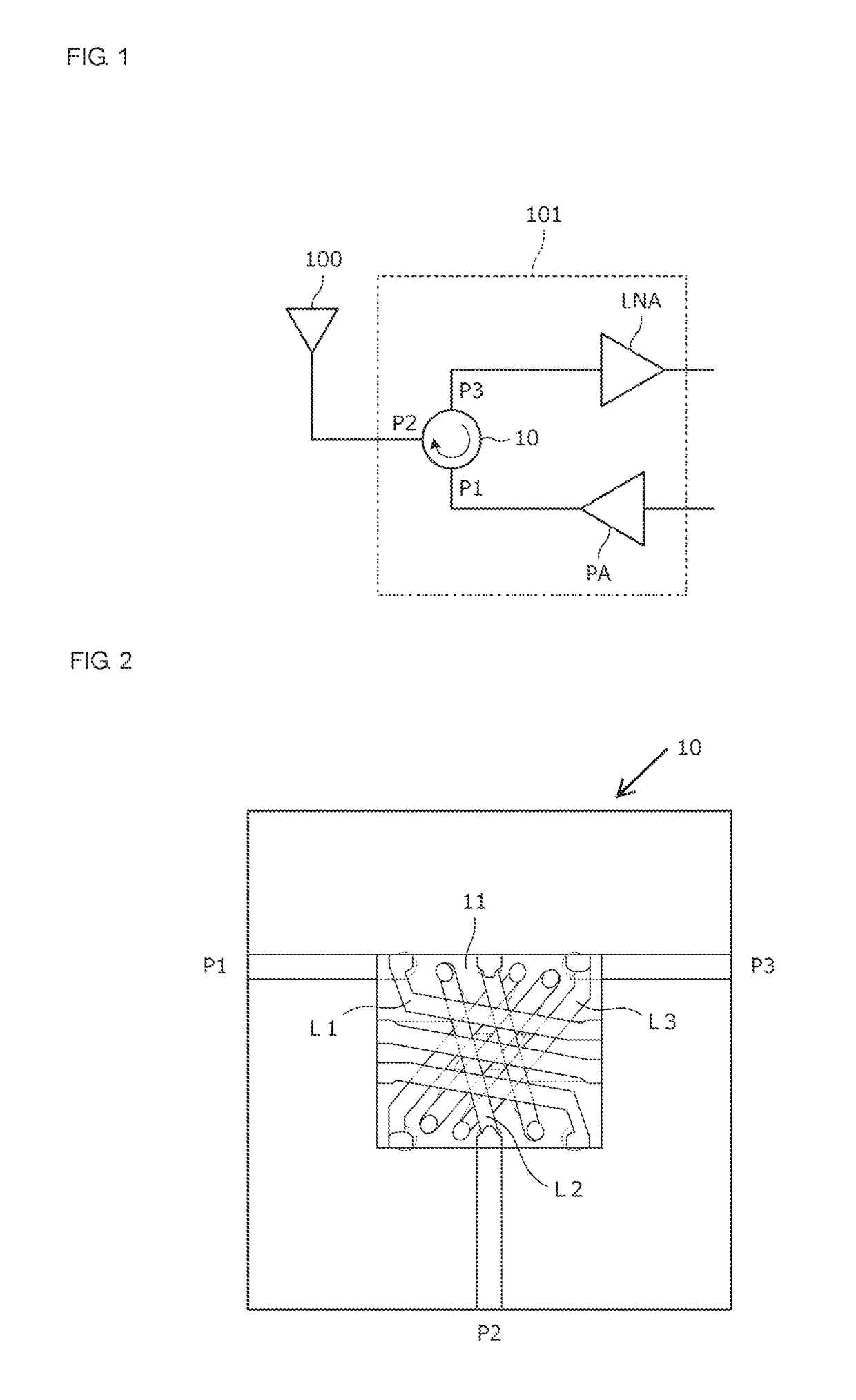
[0035]FIG. 1 is a circuit diagram of a front end circuit 101 according to the first embodiment of the present disclosure. The front end circuit 101 includes a circulator 10, a low-noise amplifier LNA, and a power amplifier PA. The power amplifier PA amplifies the power of a transmission signal. The low-noise amplifier LNA amplifies a reception signal. The circulator 10 has a first port P1 into which a transmission signal is input, a second port P2 into / from which a transmission / reception signal is input / output, and a third port P3 from which a reception signal is output. The power amplifier PA is connected to the first port P1 of the circulator 10. An antenna 100 is connected to the second port P2 of the circulator 10. The low-noise amplifier LNA is connected to the third port P3 of the circulator 10.
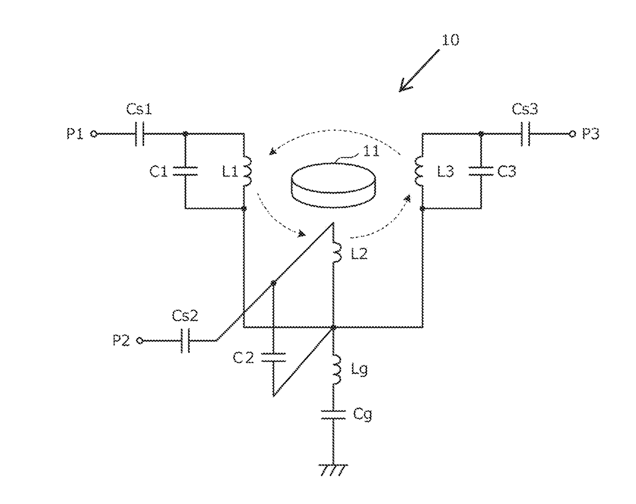
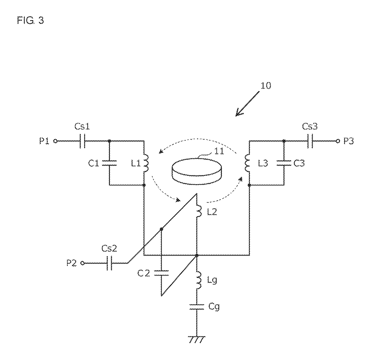
[0036]FIG. 2 is a plan view illustrating the internal structure of the circulator 10. The circulator 10 includes a ferrite plate 11, a first coil L1, a second coil L2, and a third coil ...
second embodiment
[0065]FIG. 9A is a circuit diagram of a front end circuit 102A according to the second embodiment of the present disclosure. FIG. 10A is a diagram illustrating the frequency characteristics of a reflection coefficient when an antenna side is viewed from the second port P2 of the circulator 10. FIG. 10B is a Smith chart illustrating the frequency characteristics of a reflection coefficient.
[0066]An antenna installed in a small-sized communication apparatus usually changes from capacitive nature to inductive nature while having a low radiation resistance at the time of a frequency sweep as illustrated in FIG. 10B.
[0067]It is assumed that the impedance of the second port P2 of a circulator is set to the position (17.5Ω) of a circle. In a case where a reactance element is inserted in series with an antenna, the impedance moves in a direction represented by an arrow CW or CCW in FIG. 10B (the impedance changes). By selecting the reactance of the reactance element connected in series to t...
third embodiment
[0080]FIG. 11 is a circuit diagram of a front end circuit 103 according to the third embodiment of the present disclosure. The front end circuit 103 includes the circulator 10, a transmission filter 20, and a reception filter 30. The transmission filter 20 passes a transmission signal and blocks a reception signal. The reception filter 30 passes a reception signal and blocks a transmission signal. The transmission filter 20 is connected to the first port P1 of the circulator 10 and a transmission signal input port Pt. The reception filter 30 is connected between the third port P3 of the circulator 10 and a reception signal output port Pr.
[0081]FIG. 12 is a diagram illustrating isolation characteristics of the front end circuit 103. In FIG. 12, a horizontal axis represents an antenna VSWR and a vertical axis represents the amount of isolation (dB). This drawing illustrates characteristics in a high band (1710 to 1785 MHz).
[0082]In FIG. 12, (1) represents the characteristics of a fron...
PUM
 Abstract
Description
Claims
Application Information
 - R&D
- Intellectual Property
- Life Sciences
- Materials
- Tech Scout
- Unparalleled Data Quality
- Higher Quality Content
- 60% Fewer Hallucinations
Browse by: Latest US Patents, China's latest patents, Technical Efficacy Thesaurus, Application Domain, Technology Topic, Popular Technical Reports.
© 2025 PatSnap. All rights reserved.Legal|Privacy policy|Modern Slavery Act Transparency Statement|Sitemap|About US| Contact US: help@patsnap.com