High-frequency switch module

Active Publication Date: 2012-09-27
MURATA MFG CO LTD
View PDF5 Cites 8 Cited by
  • Summary
  • Abstract
  • Description
  • Claims
  • Application Information

AI Technical Summary

Benefits of technology

[0008]To overcome the problems described above, preferred embodiments of the present invention provide a high-frequency switch module in which an internal wiring other than a power supply wiring, a circuit element, or other wiring is easily set to have a desired impedance or electrical property and which prevents leakage of power noise through an internal ground electrode to the internal wiring other than the power supply wiring.

Problems solved by technology

A problem arises when the power noise leaks to an internal wiring other than the power supply wiring in the multilayer board.
In particular, if the power noise leaks to an internal wiring (transmission wiring) for transmitting a transmission signal when the switch IC is powered on, there is a possibility that a property degradation, such as harmonic distortion, will occur, which is a serious problem.
Thus, since the internal wiring other than the power supply wiring, a circuit element, or other wiring faces the internal ground electrode, a desired impedance or electrical property may not be obtained.
In addition, power noise may leak from the power supply wiring through the internal ground electrode to the other internal wiring.

Method used


Image

  • High-frequency switch module
  • High-frequency switch module
  • High-frequency switch module

Examples


Embodiment Construction

[0029]Hereinafter, an exemplary configuration of a high-frequency switch module according to preferred embodiments of the present invention will be described.

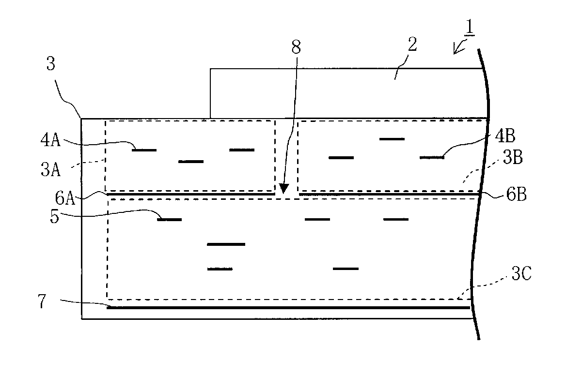
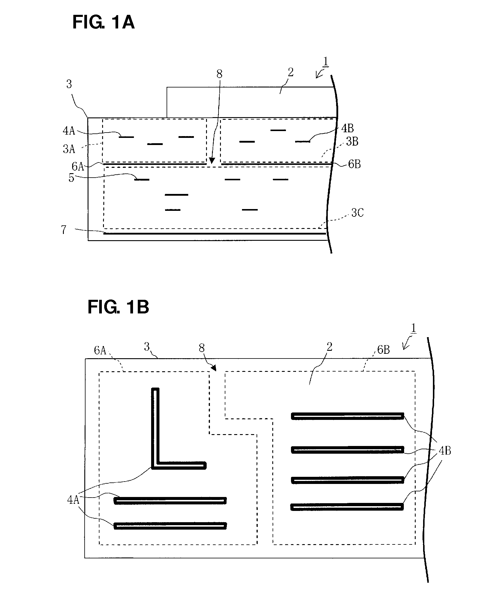
[0030]FIG. 1A is a partial cross-sectional view of the high-frequency switch module according to a preferred embodiment of the present invention, and FIG. 1B is a partial plan view of the high-frequency switch module according to the present preferred embodiment as viewed from a predetermined board interface.

[0031]The high-frequency switch module 1 preferably includes a switch IC 2 and a multilayer board 3.

[0032]The multilayer board 3 preferably includes a plurality of internal wirings 4A, 4B, and 5 and a plurality of internal ground electrodes 6A, 6B, and 7. On a top surface of the multilayer board 3, surface electrodes (not shown) for mounting a plurality of chip elements including the switch IC 2 are preferably provided. On a bottom surface of the multilayer board 3, mounting electrodes (not shown) are preferably provided.

[0...


PUM


Abstract

In a high-frequency switch module, a switch IC is mounted on a multilayer board to define a high-frequency switch module. The multilayer board includes two internal wirings and two internal ground electrodes. The internal ground electrodes are spaced apart from each other at an interval when viewed from a lamination direction of the multilayer board. The first internal wiring is located on the upper surface side of the first internal ground electrode, and is entirely separated from an RF wiring, and the first internal wiring includes a power supply wiring for supplying power to the switch IC. The second internal wiring is located on the upper surface side of the second internal ground electrode, and is entirely separated from the power supply wiring, and the second internal wiring includes a signal wiring through which an RF signal propagates.

Description

BACKGROUND OF THE INVENTION[0001]1. Field of the Invention[0002]The present invention relates to a high-frequency switch module including a switch IC that is mounted on a multilayer board.[0003]2. Description of the Related Art[0004]High-frequency switch modules are used in front end portions of mobile phones and other suitable devices. A high-frequency switch module includes a multilayer board and a switch IC mounted thereon. The switch IC connects a selected terminal selected from among a plurality of terminals to a shared terminal. The multilayer board includes surface electrodes connected to terminals of the switch IC, mounting electrodes, and internal electrodes.[0005]In a high-frequency switch module, power noise generated in the outside or in the switch IC may be superimposed on an internal wiring (power supply wiring) for supplying power to the switch IC. A problem arises when the power noise leaks to an internal wiring other than the power supply wiring in the multilayer bo...

Claims


Application Information

Patent Timeline
IPC IPC(8): H03K17/56
CPCH01P1/10H01P1/15H05K2201/09972H05K1/0237H05K2201/09663H05K1/0227
Inventor MURASE, HISANORIUEJIMA, TAKANORI
Owner MURATA MFG CO LTD
Why Eureka
Try Eureka