
Hemodialyzer for blood purification

a hemodialysis and blood technology, applied in the field of dialyzers, can solve the problems of limiting the usability and/or benefit of hdf treatment, hdf application is therefore not advisable, and high blood flow is more difficult to obtain, so as to improve the retention of albumin, reduce the difficulty of hdf treatment, and improve the effect of uremic solute removal

Active Publication Date: 2017-06-15
GAMBRO LUNDIA AB
View PDF7 Cites 6 Cited by
  • Summary
  • Abstract
  • Description
  • Claims
  • Application Information

AI Technical Summary

Benefits of technology

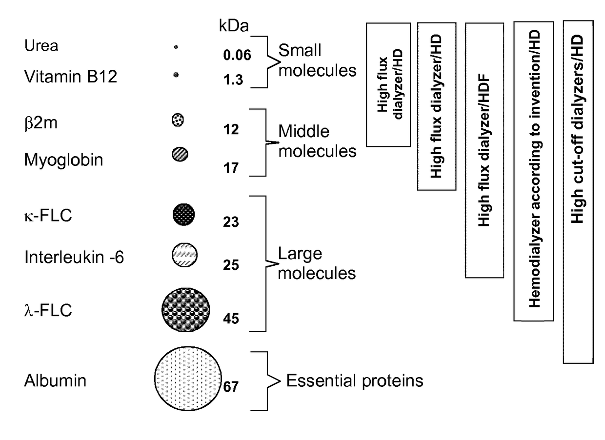
The present invention provides an improved hemodialysis filter that can efficiently remove small uremic molecules from blood, enhance the removal of middle and large uremic solutes, and retain albumin in larger proteins. The improved design of the filter includes a new hollow fiber membrane with specific molecular retention onset and molecular weight cut-off values and an overall design that boosts the removable range of uremic solutes while safely using with patients suffering from renal failure. The membrane is made of polysulfone-based, polyethersulfone-based or poly(aryl)ethersulfone-based synthetic membranes produced without treating them with a salt solution before drying. The invention is also directed to methods of using the filter device in blood purification applications.

Problems solved by technology

However, a considerable number of patients are older, diabetic and / or with a poor vascular access; in this situation high blood flows are more difficult to get at the expense of lower postdilution exchange volumes, thus limiting the usability and / or benefit of HDF treatment.
Their use in HDF application is therefore not advisable because especially in convective procedures, such as hemodiafiltration, their albumin leakage is too high.
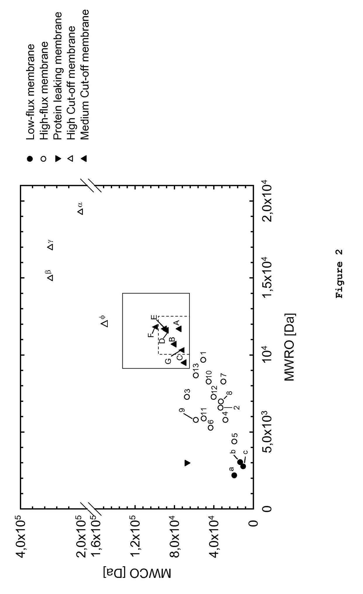
(2013) that there exists a gap between the currently known high cut-off and high-flux membranes, which so far could not be addressed by currently available membranes and dialyzers containing them.
However, to date, no such membranes or hemodialyzers have been described or prepared, even though continuous attempts have been made to produce such membranes (see, for example, EP 2 253 367 A1).
So far, no available membrane was able to, fulfil the above described expectations as regards MWRO and MWCO.

Method used


Image

  • Hemodialyzer for blood purification
  • Hemodialyzer for blood purification
  • Hemodialyzer for blood purification

Examples


example 1

Preparation of Membranes

1.1 Membrane A

[0067]Two solutions were used for the formation of the membrane, the polymer solution consisting of hydrophobic and hydrophilic polymer components dissolved in N-methyl-pyrrolidone, and the center solution being a mixture of N-methyl-pyrrolidone (NMP) and water. The polymer solution contained poly(aryl)ethersulfone (PAES 14.0 wt-%) and polyvinylpyrrolidone (2 wt-% of PVP K85 and 5 wt-% of PVP K30, a total PVP concentration in the polymer solution of 7 wt-%). The solution further contained NMP (77.0 wt-%) and water (2.0 wt-%). The viscosity of the polymer solution, measured at a temperature of 22° C., was between 5500 and 5700 mPas. The spinneret was heated to a temperature of 59° C. The center solution contained water (54.5 wt-%) and NMP (45.5 wt-%). A defined and constant temperature regime was applied to support the process. The center solution was pre-heated to 59° C. and pumped towards the two-component hollow fiber spinneret. The polymer so...

example 2

Preparation of Filters, Hand Bundles and Mini-Modules; Measurement of Sieving Coefficients

2.1 Preparation of Filter, Hand-Bundles and Mini-Modules

[0095]Filters can be prepared by introducing a fiber bundle into a dialyser housing. The bundle is potted with polyurethane, ends are cut, on both sides of the dialyser a header is fixed to the housing, the dialyser is rinsed with hot water and dried with air. During this last drying step, a certain amount of about between 10 g and 30 g of residual water per m2 effective membrane area is left on the dialyser. After labelling and packaging, the dialyser can be steam-sterilized within the packaging in an autoclave at 121° C. for at least 21 min.

[0096]The preparation of a hand bundle after the spinning process is necessary to prepare the fiber bundle for following performance tests with mini-modules. The first process step is to cut the fiber bundles to a defined length of 23 cm. The next process step consists of melting the ends of the fiber...

example 3

Dextran Sieving Measurements

3.1 Dextran Solutions

[0100]Fractions of dextran supplied by Fluka (Mw 6, 15-20, 40, 70, 100, 200, 500 kDaa) and Sigma-Aldrich (Mw 9-11 kDaa) (both from Sigma-Aldrich Co. LLC, St. Louis, USA) were used without further purification. Solutions of dextrans with the different molecular weight fractions were combined in Millipore water (i.e., Type 1 ultrapure water, as defined by ISO 3696) at a concentration of 1 g / l for each fraction, which results in an overall concentration of 8 g / l.

3.2 Devices and Sample Preparation

[0101]For characterizing the membranes according to the invention and comparing them with membranes known from the prior art, it was necessary to eliminate the differences between devices caused by having different membrane surface areas or fiber numbers. Therefore, standardized mini-modules with a surface area of from 280 cm2 to 300 cm2 were manufactured from the membranes according to the invention or from membranes according to the prior art. ...


PUM

PropertyMeasurementUnit
Fractionaaaaaaaaaa
Fractionaaaaaaaaaa
Fractionaaaaaaaaaa

Abstract

The present disclosure relates to a dialyzer comprising a bundle of semipermeable hollow fiber membranes which is suitable for blood purification, wherein the dialyzer has an increased ability to remove larger molecules while at the same time it is able to effectively remove small uremic toxins and efficiently retain albumin and larger proteins. The invention also relates to using said dialyzer in hemodialysis.

Description

TECHNICAL FIELD[0001]The present disclosure relates to a dialyzer comprising a bundle of semipermeable hollow fiber membranes which is suitable for blood purification, wherein the dialyzer has an increased ability to remove larger molecules while at the same time it is able to effectively remove small uremic toxins and efficiently retain albumin and larger proteins. The invention also relates to using said dialyzer in hemodialysis.DESCRIPTION OF THE RELATED ART[0002]Capillary dialyzers are widely used for blood purification in patients suffering from renal insufficiency, i.e., for treatment of the patients by hemodialysis, hemodiafiltration or hemofiltration.[0003]The devices generally consist of a casing comprising a tubular section with end caps capping the mouths of the tubular section. A bundle of hollow fiber membranes is arranged in the casing in a way that a seal is provided between the first flow space formed by the fiber cavities and a second flow space surrounding the memb...

Claims


Application Information

Patent Timeline
IPC IPC(8): B01D71/68A61M1/34B01D69/08B01D71/38B01D61/24B01D63/02
CPCB01D71/68B01D61/243B01D63/021B01D69/084B01D69/087B01D2323/06A61M1/3479B01D2323/12B01D2325/20B01D2325/022B01D71/38B01D71/44B01D63/0233B01D71/441B01D71/381
Inventor HORNUNG, MARKUSKRAUSE, BERNDSTORR, MARKUSHERBST, PHILIPPWOCHNER, ARNDBOSCHETTI-DE-FIERRO, ADRIANAVOIGT, MANUELZWEIGART, CARINALOERCHER, JOACHIMBUCK, REINHOLDBEHR, HEINRICHBECK, WERNER
Owner GAMBRO LUNDIA AB
Learn More