
Optical film and optical laminate using same

a technology of optical laminates and optical films, applied in the field of optical films, can solve the problems of difficult removal of sebum or the like adhesion to a multi-layer film, peeling of the multi-layer film, and difficulty in obtaining reflection abilities comparable to an interface with the outside air, so as to minimize the polarity of a polarizing element due to circular polarization light

Active Publication Date: 2017-06-08
NIPPON KAYAKU CO LTD +2
View PDF13 Cites 4 Cited by
  • Summary
  • Abstract
  • Description
  • Claims
  • Application Information

AI Technical Summary

Benefits of technology

The present invention provides an optical film that can minimize the decrease in polarization caused by circularly polarized light. Additionally, the film prevents extrinsic factors such as sebum, moisture, and salt air from affecting the glasses, ensuring a consistent metallic hue for an extended period.

Problems solved by technology

While imparting a multilayer film in this manner is advantageous for the wearer, a problem in terms of handling, specifically, that sebum or the like adhering to a multilayer film is difficult to remove, or a problem of peeling of the multilayer film in locations of exposure to moisture such as seawater or to salt air, was sometimes encountered.
However, because the reflecting abilities of a multilayer film are produced by differences in refractive index between the layers, it is difficult to obtain reflecting abilities comparable to an interface with the outside air.
Moreover, because multilayer films comprise inorganic substances, adhesion to polarizing elements, which are organic, can be a problem.

Method used


Image

  • Optical film and optical laminate using same
  • Optical film and optical laminate using same
  • Optical film and optical laminate using same

Examples


example 1

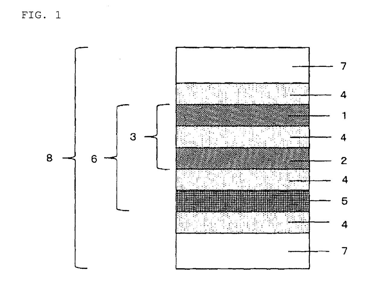
[0063]Using the prepared coating liquids (R1) and (L1), each of the light-reflecting layers was prepared by the procedure indicated below, and these were then laminated to prepare laminates having the light-reflecting layers employed in the present invention. PET film (no undercoat layer) manufactured by Toyobo Co. Ltd. was used as a plastic substrate.

(1) Using a wire bar, each coating liquid was applied at room temperature to the PET film, to a post-drying film thickness of 4 μm.

(2) Product was heated for 5 minutes at 150° C. to eliminate the solvent and produce a cholesteric liquid crystal phase. Next, product was irradiated with UV for 5-10 seconds at 120 W output from a high-pressure mercury lamp (manufactured by Harison Toshiba Lighting Corp.), and the cholesteric liquid crystal phase was fixed, to obtain the light-reflecting layer.

(3) The light-reflecting layers (R1) and light-reflecting layers (L1) prepared in steps (1) and (2) were laminated together from the light-reflectin...

example 2

[0072]A laminate of the light-reflecting layers employed in present invention were prepared by the same operation as in Example 1, except for using the prepared coating liquids (R2) and (L2). The center reflection wavelength of the light-reflecting layer (R2) and the light-reflecting layer (L2) was 540 nm. Next, the laminate was laminated to a polarizing element in the same way as in Example 1, to obtain an optical film of the present invention. The optical film was measured as to polarization in the same manner as in Example 1; the result was polarization of 98.1%.

example 3

[0073]A laminate of the light-reflecting layers employed in present invention were prepared by the same operation as in Example 1, except for using the prepared coating liquids (R3) and (L3). The center reflection wavelengths of the light-reflecting layer (R3) and the light-reflecting layer (L3) were 650 nm and 630 nm, respectively. Next, the laminate was laminated to a polarizing element in the same way as in Example 1, to obtain an optical film of the present invention. The optical film was measured as to polarization in the same manner as in Example 1; the result was polarization of 98.3%.


PUM


Abstract

[Problem] The present invention provides eyewear, such as polarized sunglasses, having cholesteric liquid crystal layers, wherein the eyewear has a metallic tone and antiglare properties, minimizes the reduction in light-polarizing element absorptive capability that is associated with circular polarization, and is moreover unaffected by external degrading factors such as sebum, moisture, and salt air.[Solution] This optical film is characterized by being provided with a light-reflecting layer R comprising a cholesteric liquid crystal layer that has right-handed helical orientation, a light-reflecting layer L comprising a cholesteric liquid crystal layer that has left-handed helical orientation, and a polarizing element layer.

Description

TECHNICAL FIELD[0001]The present invention relates to an optical film provided with a light-reflecting layer for reflecting visible light, and a polarizing element, and primarily intended for utilization in eyewear (sunglasses, goggles, helmet visors, and the like).BACKGROUND ART[0002]Eyewear (sunglasses, goggles, visors, and the like) is employed for reducing glare caused by reflected light from water, road surfaces, snow, and the like. For example, with sunglasses, the lens parts are tinted with pigments or the like so as to reduce the amount of light entering the eyes and reduce glare, through absorption of light by the pigment. Polarized sunglasses are particularly effective against reflected light from water, snow, and the like.[0003]Because reflected light is polarized light, polarized sunglasses are designed to effectively absorb light in the polarization direction thereof, so that glare can be reduced and visibility improved without significantly reducing the amount of light...

Claims


Application Information

Patent Timeline
IPC IPC(8): G02C7/12G02B27/28G02C7/10G02B5/30
CPCG02C7/12G02B5/3016G02C7/108G02B27/288G02B5/3041G02C7/10G02B5/30
Inventor TANAKA, KOUICHIYAHAGI, YOSHIYUKIFUJISAWA, HIDEYOSHIGOTOU, TAKUYAMURAI, KATSUYUKIMITSUHATA, KAZUHISANAKAMURA, KYOUSUKE
Owner NIPPON KAYAKU CO LTD
Learn More