
Device for the production of fuel gas from materials of organic and/or inorganic origin

a technology of fuel gas and organic materials, which is applied in the direction of combustible gas production, gasification process details, thermal treatment of fuel, etc., can solve the problems of high ash and other pollutants, difficult to precisely regulate the combustion process, and low moistur

Active Publication Date: 2017-06-08
JANCOK LUBOR
View PDF28 Cites 4 Cited by
  • Summary
  • Abstract
  • Description
  • Claims
  • Application Information

AI Technical Summary

Benefits of technology

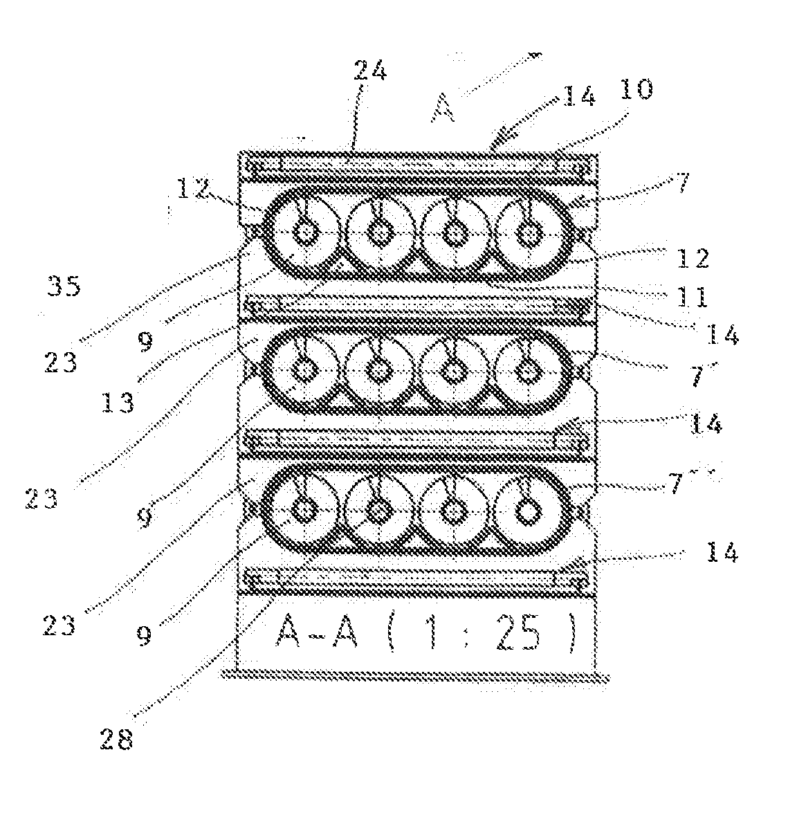
The invention is a device for producing high-quality synthesis gas with a low content of tars and nitrogen. It uses electric heating to process materials with a high moisture content and prevents the inlet of atmospheric air. The device includes gasification bodies with heating elements, separating them with vertical supporting partitions, and a module for moisturizing and preheating the material before its entry into the gasification bodies. The front wall of each gasification body is connected to the gasification augers' axles. The device has low emissions, efficient gasification process regulation, and improved reactor system stability.

Problems solved by technology

In these known devices, the major problem is maintaining the stability of the gasification process and achieving a standard high quality of the output synthesis gas, particularly in achieving a low tar and nitrogen content.
Precise regulation of the combustion process is difficult, and a disadvantage also lies in the high emissions of ash and other pollutants.
Low moisture, which is a prerequisite of effective combustion, has the undesirable consequence of a high tar content which must subsequently be chemically removed by washing in order to achieve a sufficient quality of synthesis gas for its combustion in internal combustion engines.
During the combustion of the material, which must have a low input relative moisture, undesirable tars are not formed but neither is a large percentage of nitrogen, so the output synthesis gas is not of a sufficient quality.
Given that the gasification augers are not hermetically separated from the combustion auger, the disadvantage of the device is that part of the flue gas continuously penetrates into the gasification augers, so the nitrogen content in the exhaust gas cannot achieve the zero or negligible value optimal for achieving a high quality of developed synthesis gas.

Method used


Image

  • Device for the production of fuel gas from materials of organic and/or inorganic origin
  • Device for the production of fuel gas from materials of organic and/or inorganic origin
  • Device for the production of fuel gas from materials of organic and/or inorganic origin

Examples


Embodiment Construction

OF THE PREFERRED EMBODIMENT OF THE INVENTION

[0025]It should be understood that the further described and illustrated specific examples of the realized invention are presented for illustrative purposes and not as a limitation of the examples of the realization of the invention to the cases shown herein. Those skilled in the art shall find, or using routine experimentation will be able to determine, a greater or lesser number of equivalents to the specific realizations of the invention that are specifically described here. These equivalents shall also be included into the scope of the following claims.

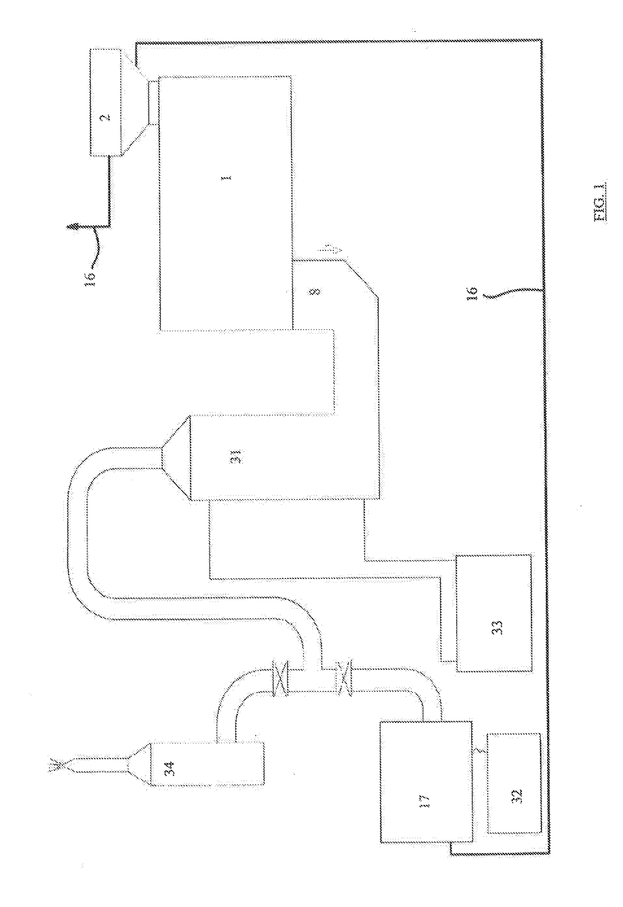
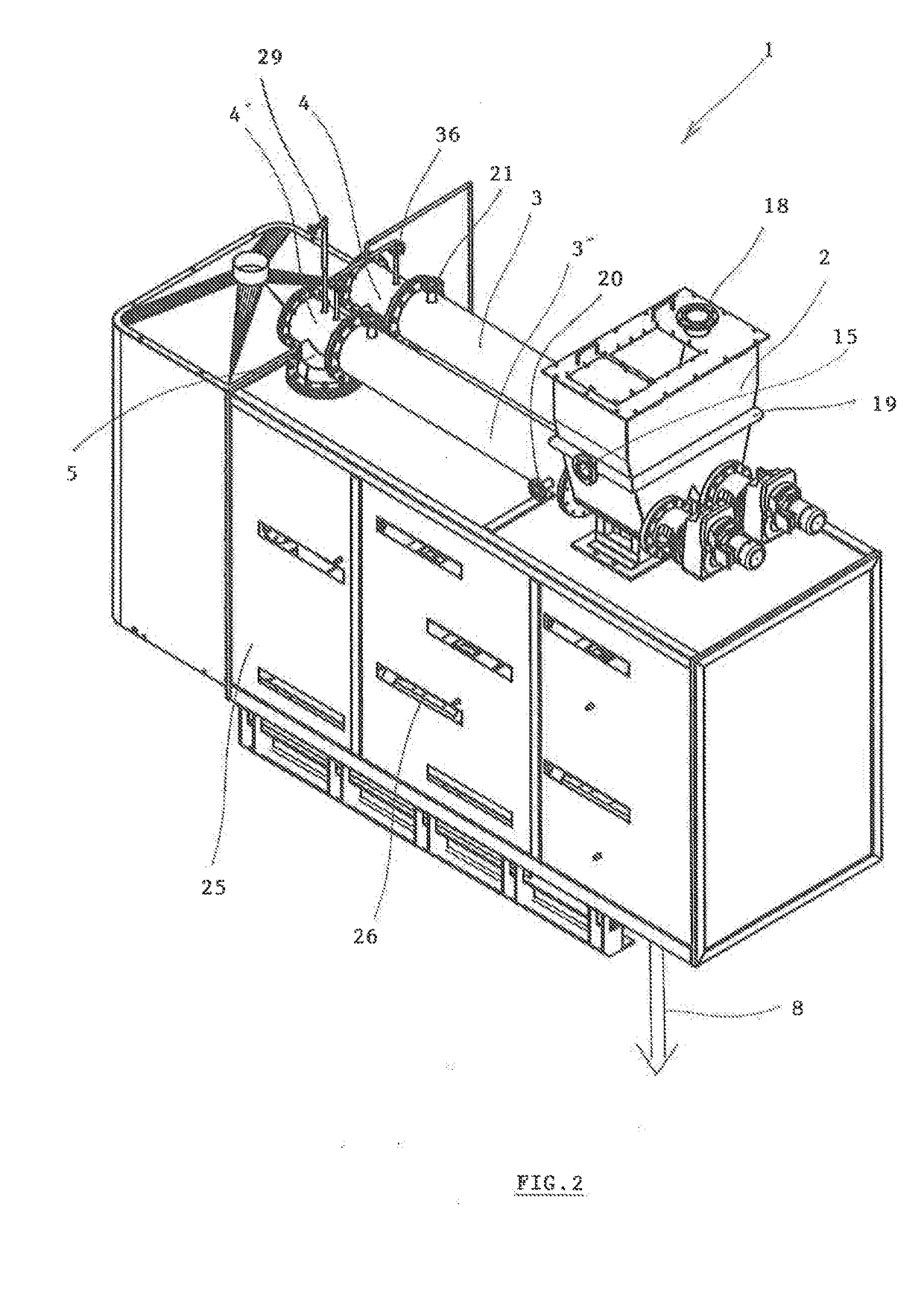
[0026]The device 1 is, in the embodiment shown in FIG. 1, part of a technological system used to produce electricity from biomass. Electrical energy is produced by a generator which is part of a cogeneration unit connected to a transformer 32. The generator is powered by a combustion engine 17, which is continuously supplied by gaseous fuel produced in the device 1 as synthesis gas forme...


PUM

PropertyMeasurementUnit
stabilityaaaaaaaaaa
combustionaaaaaaaaaa
timeaaaaaaaaaa

Abstract

A device for producing fuel gas from materials of organic and / or inorganic origin, comprising filling chamber connected to at least one supply auger conveyor for supplying material from the filling chamber into a reactor comprising at least two heated gasification augers. The invention consists in the fact that each horizontal row of gasification augers is formed by a gasification body, the casing of which has a closed oval cross-section formed by an upper base, a lower base, and convex side walls each with circular arc profiles, wherein each gasifying body contains at least two gasification augers arranged side by side and mutually partially separated by longitudinal partitions that form half-grooves for gasifying augers. The device is provided with at least one electrical heater. The filling chamber is hermetically sealed.

Description

BACKGROUND AND SUMMARY OF THE INVENTION[0001]The invention relates to a device for the gasification of organic or inorganic materials such as bulk waste based on wood or other biomass, or even municipal waste, waste oil, coal, etc., which generates synthesis gas used as fuel for internal combustion engines and combustion turbines, for example those designed to drive electric generators in cogeneration units.[0002]Hitherto known devices for the gasification of organic or predominantly organic materials such as wood waste, wood chips, straw, sludge, and various forms of biomass, including municipal and other wastes, predominantly utilize a gasification process based on combustion, partial combustion, or fluidized bed combustion of material. In these cases the material is filled from a filling hopper into auger conveyors, through which it is moved and is heated directly or indirectly during the passage through the auger conveyors, during which synthesis gas is developed from the ongoin...

Claims


Application Information

Patent Timeline
Patent Type & Authority Applications(United States)
IPC IPC(8): C10J3/20C10J3/32F02M31/18
CPCC10J3/20F02M31/18C10J3/32C10J2300/1276C10J2300/1853C10J2300/0973C10J2300/0976C10J2300/1671C10J2300/0916C10J3/007C10J2300/1246C10J2200/158Y02E50/10Y02T10/12
Inventor JANCOK, LUBOR
Owner JANCOK LUBOR
Learn More