
Engine mount

a technology for mounting engines and mounts, applied in the direction of functional valve types, shock absorbers, jet propulsion mounting, etc., can solve the problems of limited simultaneous attenuation of general hydraulic mounts, increased consumption current, negative effect on fuel efficiency, etc., to improve damping performance and noise, reduce dynamic characteristics, and increase the coefficient of loss

Active Publication Date: 2017-06-01
HYUNDAI MOTOR CO LTD
View PDF7 Cites 13 Cited by
  • Summary
  • Abstract
  • Description
  • Claims
  • Application Information

AI Technical Summary

Benefits of technology

The present invention is an engine mount that can adjust the flow of hydraulic fluid based on different driving conditions, even without a drive mechanism. The engine mount has both volume-stiffness and bypass-type features to improve its performance. This allows for increased efficiency in attenuating visions and reducing noise, vibration, and harshness. Overall, the engine mount of the present invention combines the best of both worlds to provide improved performance.

Problems solved by technology

However, since vibrations generated in a vehicle may be transmitted through the road surface as well as through the engine and the characteristics of the generated vibrations may vary based on the conditions in which the vehicle is being driven, the use of a general hydraulic mount is limited to the simultaneous attenuation of vibrations having different frequency ranges.
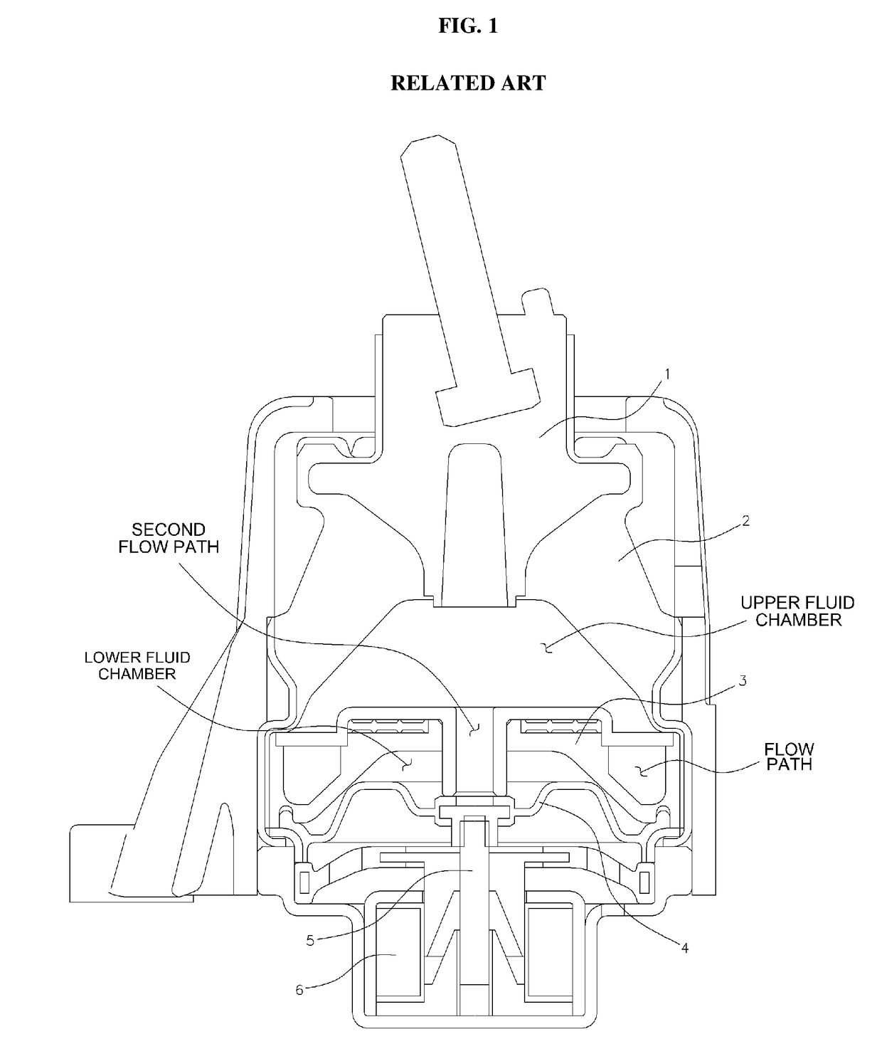
However, since the active mount requires the additional mounting of a drive mechanism (e.g., including the rod, spring, coil and power application device) to the fluid-filled mount, consumption current is increased due to the addition of the drive mechanism, which may have a negative effect on fuel efficiency and may result in increased production costs and weight.

Method used


Image

  • Engine mount
  • Engine mount
  • Engine mount

Examples


Embodiment Construction

[0023]It is understood that the term “vehicle” or “vehicular” or other similar term as used herein is inclusive of motor vehicles in general such as passenger automobiles including sports utility vehicles (SUV), buses, trucks, various commercial vehicles, watercraft including a variety of boats and ships, aircraft, and the like, and includes hybrid vehicles, electric vehicles, combustion, plug-in hybrid electric vehicles, hydrogen-powered vehicles and other alternative fuel vehicles (e.g. fuels derived from resources other than petroleum).

[0024]The terminology used herein is for the purpose of describing particular embodiments only and is not intended to be limiting of the invention. As used herein, the singular forms “a”, “an” and “the” are intended to include the plural forms as well, unless the context clearly indicates otherwise. It will be further understood that the terms “comprises” and / or “comprising,” when used in this specification, specify the presence of stated features,...


PUM


Abstract

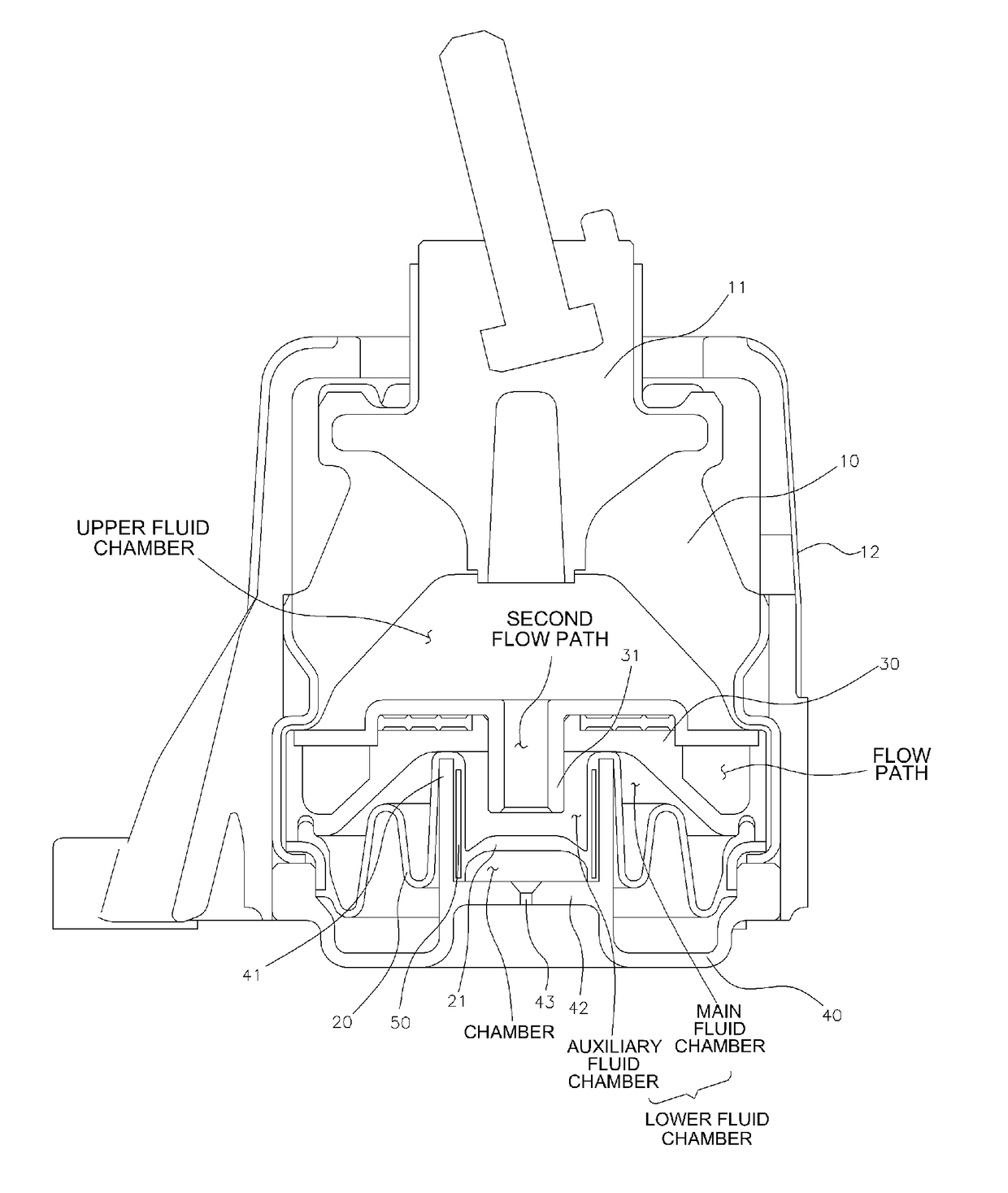
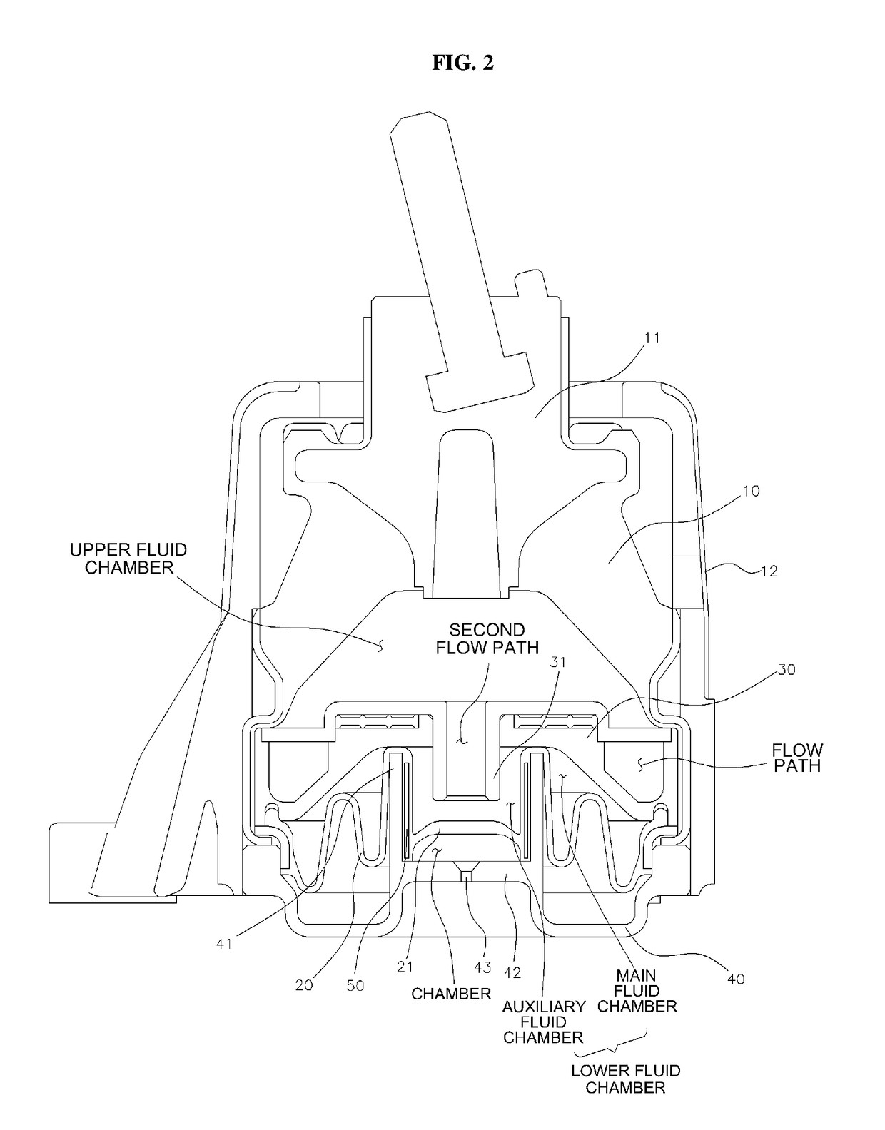
An engine mount is provided that includes a nozzle plate that is mounted between an insulator and a diaphragm to divide the interior into upper and lower fluid chambers to enable the flow of hydraulic fluid between the chambers through a first flow path formed in the nozzle plate according to variation in the volume of the interior. The nozzle plate includes a second flow path and a division cup that has an upwardly protruding portion to push the diaphragm to divide the lower fluid chamber into a main fluid chamber communicating with the flow path and an auxiliary fluid chamber communicating with the second flow path. A partition is formed inside the protruding portion to form a chamber below the auxiliary fluid chamber, and an introduction / discharge aperture is formed in the partition to enable introduction or discharge of air into or from the chamber.

Description

CROSS-REFERENCE TO RELATED APPLICATION[0001]This application claims the priority benefit of Korean Patent Application No. 10-2015-0169635, filed on Dec. 1, 2015 in the Korean Intellectual Property Office, the disclosure of which is incorporated herein by reference.BACKGROUND[0002]1. Field of the invention[0003]The present invention relates to an engine mount mounted to attenuate vibrations generated in an engine and to support the weight of the engine, and more particularly, to an engine mount having a self-variation property, which may vary vibration attenuation characteristics based on driving conditions even when a separate drive mechanism is not provided, thereby more efficiently attenuating vibrations within different frequency ranges.[0004]2. Description of the Related Art[0005]A general hydraulic mount (e.g., fluid-filled mount) is typically filled with a predetermined amount of hydraulic fluid to attenuate vibrations via the flow of the hydraulic fluid. The hydraulic mount e...

Claims


Application Information

Patent Timeline
Patent Type & Authority Applications(United States)
IPC IPC(8): F16F13/10B60K5/12
CPCF16F13/107B60K5/1208F16F13/10B60K5/1216F16F15/04F16K15/04F16F13/20
Inventor KIM, SEUNG-WON
Owner HYUNDAI MOTOR CO LTD
Learn More