
Implant placement systems, devices and methods

Active Publication Date: 2017-06-01
TENJIN
View PDF1 Cites 4 Cited by
  • Summary
  • Abstract
  • Description
  • Claims
  • Application Information

AI Technical Summary

Benefits of technology

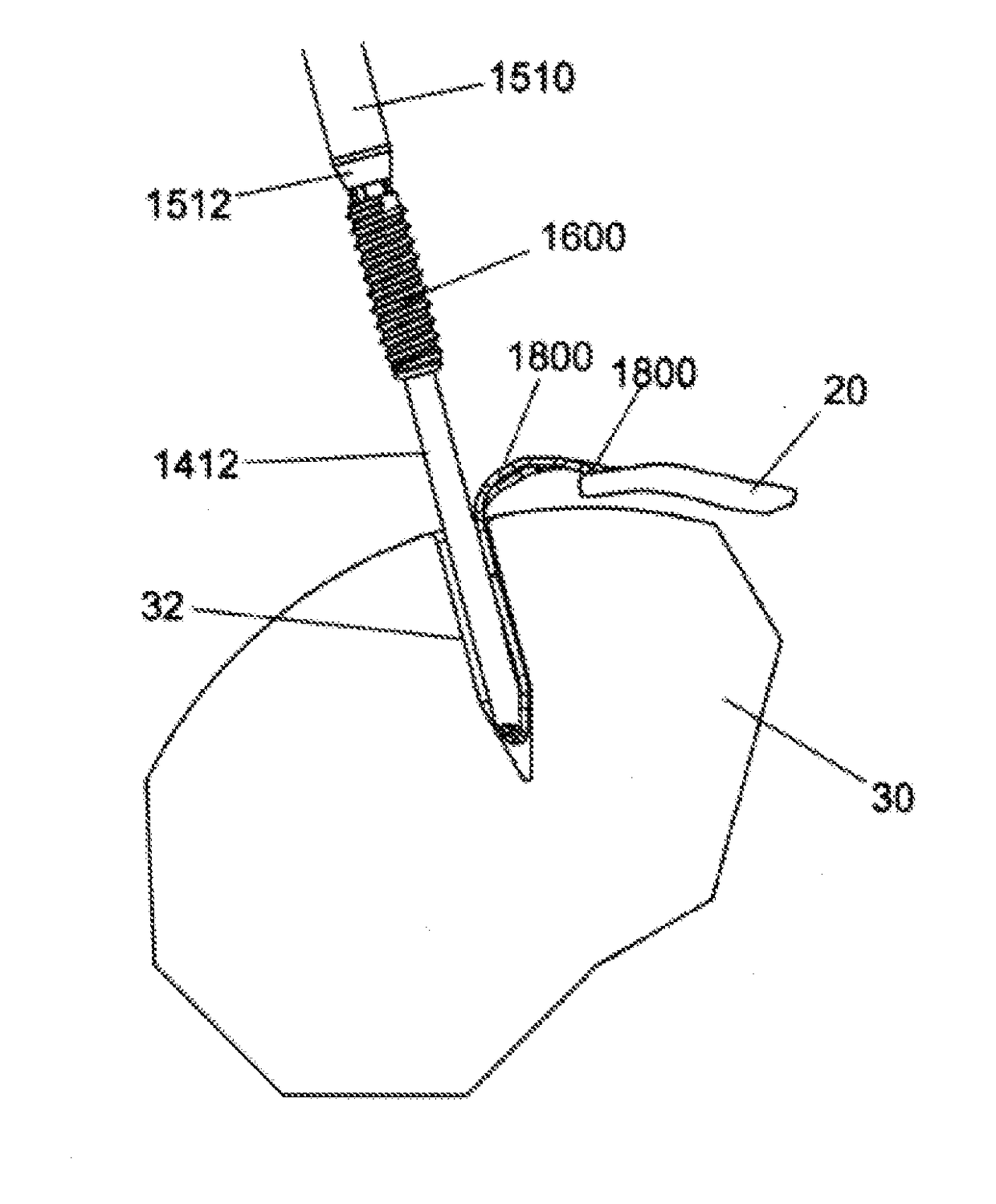
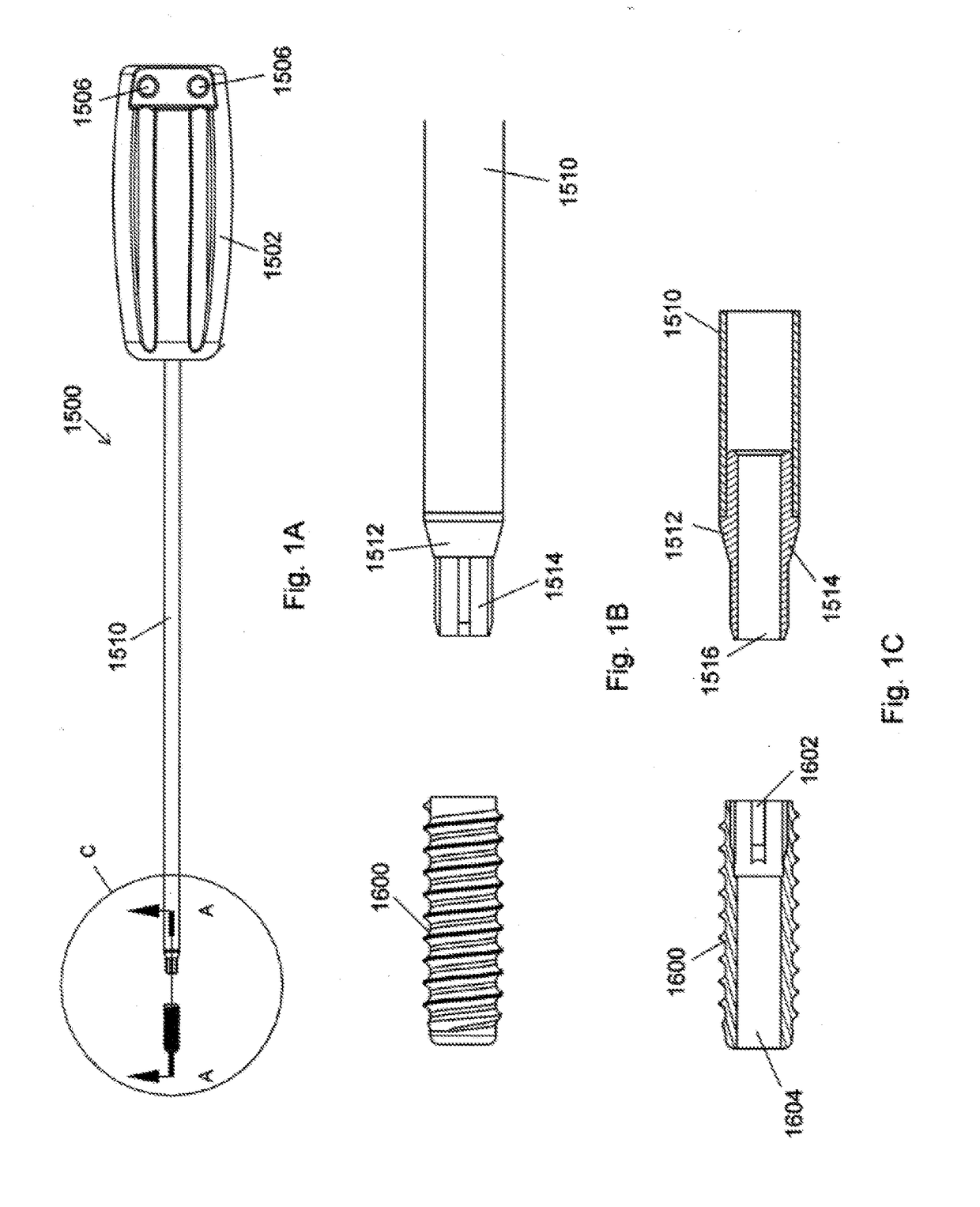
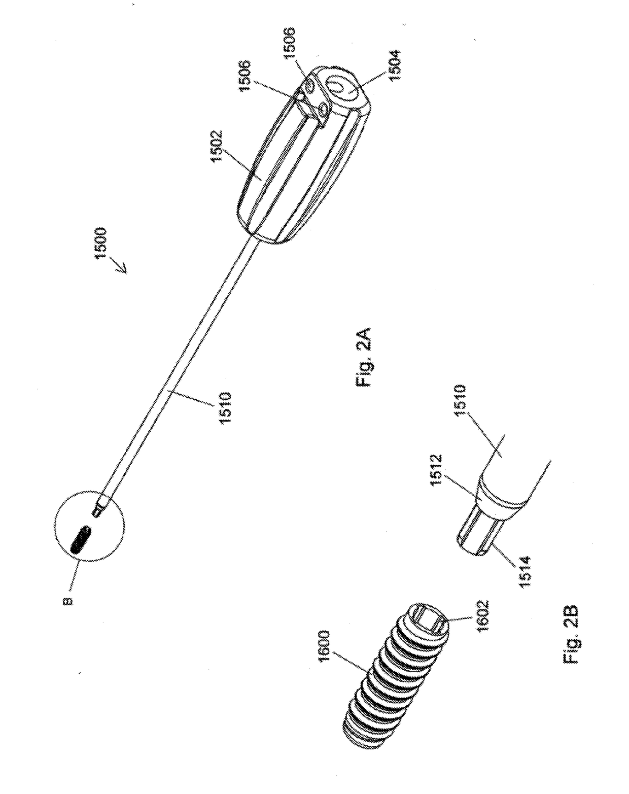
The present invention provides an improved method and system for anchoring sutures and grafts in bones. The system includes a tensioning device and an anchor that work together to secure the graft in place. The tensioning device is placed at the distal end of a driver and is used to draw the sutures into the bone. The anchor is then driven into the bone to secure the graft. The system eliminates the need for torque transmission to the sutures, reducing the risk of spinning. The anchor system is scalable and can be used with smaller anchors. The system also includes a mechanism for preventing relative movement between the driver and the tensioning device during use. The graft can be pierced by sharpened members and a depth-limiting element can be used to prevent damage to the graft. The technical effects of the invention include improved anchoring efficiency, reduced risk of spinning, and simplified and scalable construction.

Problems solved by technology

In contrast to the Burkhart and ElAttrache anchor systems, suture tensioning and establishment of the graft position are not accomplished using the driver's distal end or using an implant positioned in the driver's distal end.

Method used


Image

  • Implant placement systems, devices and methods
  • Implant placement systems, devices and methods
  • Implant placement systems, devices and methods

Examples


examples

[0224]FIGS. 85 through 88 depict a prior art device and method for the placement of a knotless suture anchor. Cannulated driver 100 has a handle portion 102 and a distal hexagonal portion 104 that protrudes beyond anchor 106. Suture 108 in the cannulation of driver 100 forms a loop at the distal end of distal hexagonal portion 104. In FIG. 85, sutures 110, which have been passed through graft 112, are positioned within the distal loop of sutures 108 where they are secured against the distal end of distal hexagonal portion 104 by tension applied by the surgeon to the proximal ends of sutures 108. Alternatively, graft 112 may be positioned within the distal loop of suture 108 and secured against the distal end of distal hexagonal portion 104 and maintained in that position by tension applied to sutures 108. Substantial tension must be maintained in sutures 108 when graft 112 is secured in this manner to ensure that the position of graft 112 does not change during insertion of the graf...


PUM


Abstract

Described herein is a simplified placement system and method for a tissue graft or “suture anchor”, threaded, knotless or otherwise, by which a surgeon may introduce one or more sutures into a hole in a boney tissue, apply a precise amount of tension to the sutures to advance a soft tissue graft to a desired location, and then advance the anchor into the bone, preferably while maintaining the requisite pre-determined suture tension and without introducing spin to the suture. The simplified placement system and method of the present invention allows the surgeon to establish the graft position and, while maintaining that position, secure the anchor without changing the suture tension or causing a shift in the graft position and furthermore, when the anchor is threaded, without spinning of the suture. In certain preferred embodiments, the distal end of the device includes a resiliently deformable polymeric distal element, optionally including a “split” suture-capturing loop, that allows for the retention of multiple sutures. In other embodiments, the distal end may further include a depth or penetration-limiting element formed of a suitable metallic or polymeric material that serves to prevent the distal end of the device from excessively penetrating, damaging or tearing a tissue graft of interest.

Description

PRIORITY[0001]This application is a continuation-in-part of U.S. patent application Ser. No. 14 / 972,662 filed Dec. 17, 2015, which, in turn, is a continuation of U.S. patent application Ser. No. 14 / 636,389 filed Mar. 3, 2015 (now U.S. Pat. No. 9,226,817 issued Jan. 5, 2016), which, in turn, claims the benefit of U.S. Provisional Application Ser. Nos. 61 / 966,744 filed Mar. 3, 2014; 61 / 998,391 filed Jun. 26, 2014; 61 / 998,766 filed Jul. 7, 2014; and 61 / 999,405 filed Jul. 26, 2014, the contents of each of which are hereby incorporated by reference in their entirety. This application is also a continuation-in-part of U.S. patent application Ser. No. 15 / 012,060 filed Feb. 1, 2016, which, in turn, claims the benefit of U.S. Provisional Application Ser. Nos. 62 / 125,745 filed Jan. 30, 2015; 62 / 177,263 filed Mar. 9, 2015; 62 / 230,682 filed Jun. 11, 2015; and 62 / 284,151 filed Sep. 21, 2015, the contents of each of which are hereby incorporated by reference in their entirety.TECHNICAL FIELD OF T...

Claims


Application Information

Patent Timeline
IPC IPC(8): A61B17/04
CPCA61B17/0401A61B2017/0409A61B2017/0464A61B2017/044A61B2017/0445A61B17/0482A61B17/0485A61B17/06061A61B2017/00305A61B2017/00309A61B2017/00314A61B2017/00353A61B2017/00477A61B2017/0088A61B2017/0412A61B2017/0458A61B2017/0496A61F2/0805A61F2/0811A61F2002/0841A61F2002/0858A61F2002/0888A61B2090/064
Inventor DOUGHERTY, CHRISTOPHER P.VAN WYK, ROBERT A.HEISLER, GARY R.
Owner TENJIN
Learn More