
Liquid crystal panel, liquid crystal display device, and method for driving same

a liquid crystal display device and liquid crystal display technology, applied in the direction of instruments, static indicating devices, etc., can solve the problems of flicker and residual image phenomenon, non-uniform optimal common voltages cannot be applied to the related art liquid crystal display devices, image quality deterioration, etc., to reduce or remove residual image of initial state, reduce manufacturing cost or manufacturing time, effect of reducing or removing residual imag

Active Publication Date: 2017-05-25
LG DISPLAY CO LTD
View PDF6 Cites 19 Cited by
  • Summary
  • Abstract
  • Description
  • Claims
  • Application Information

AI Technical Summary

Benefits of technology

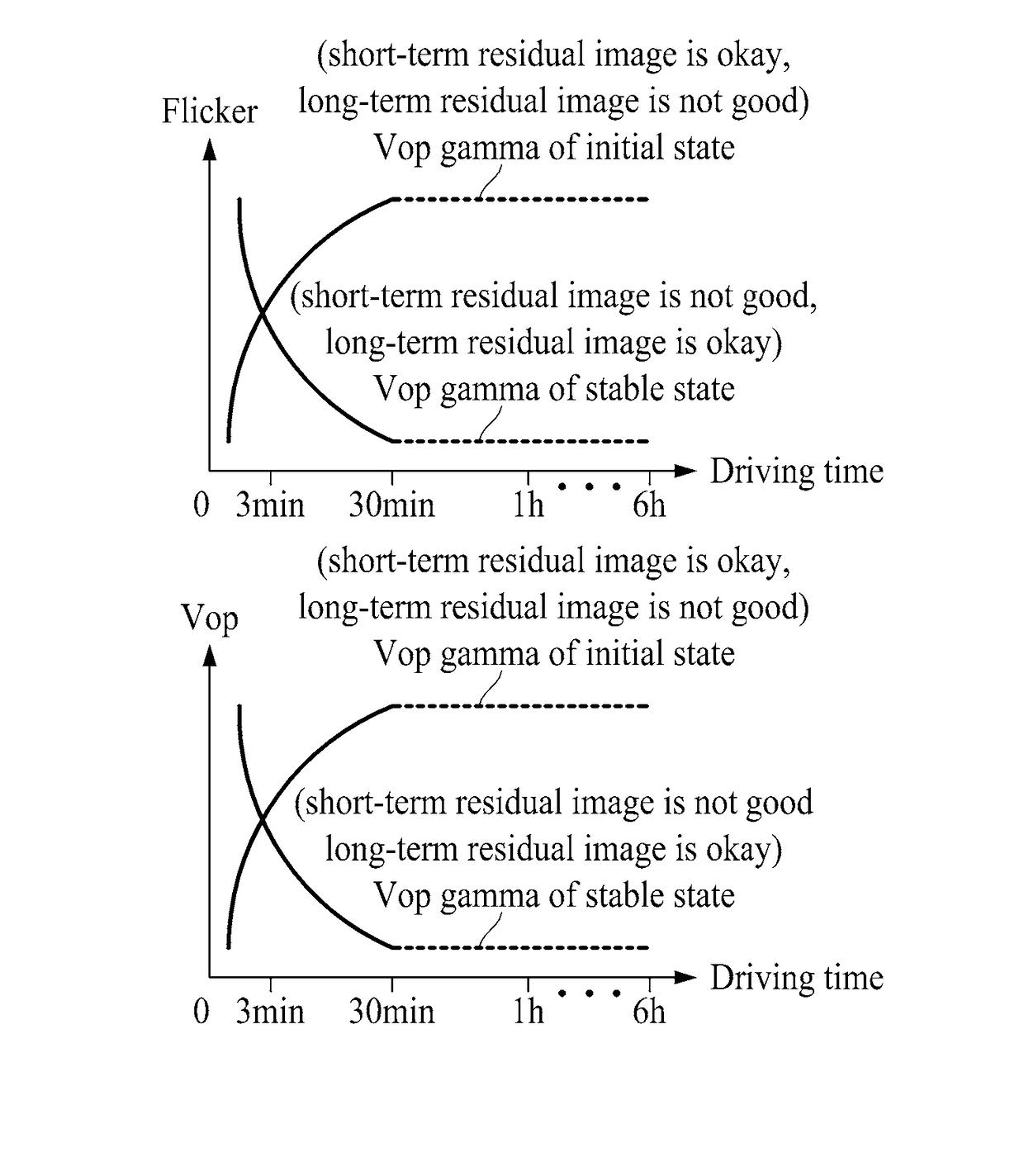
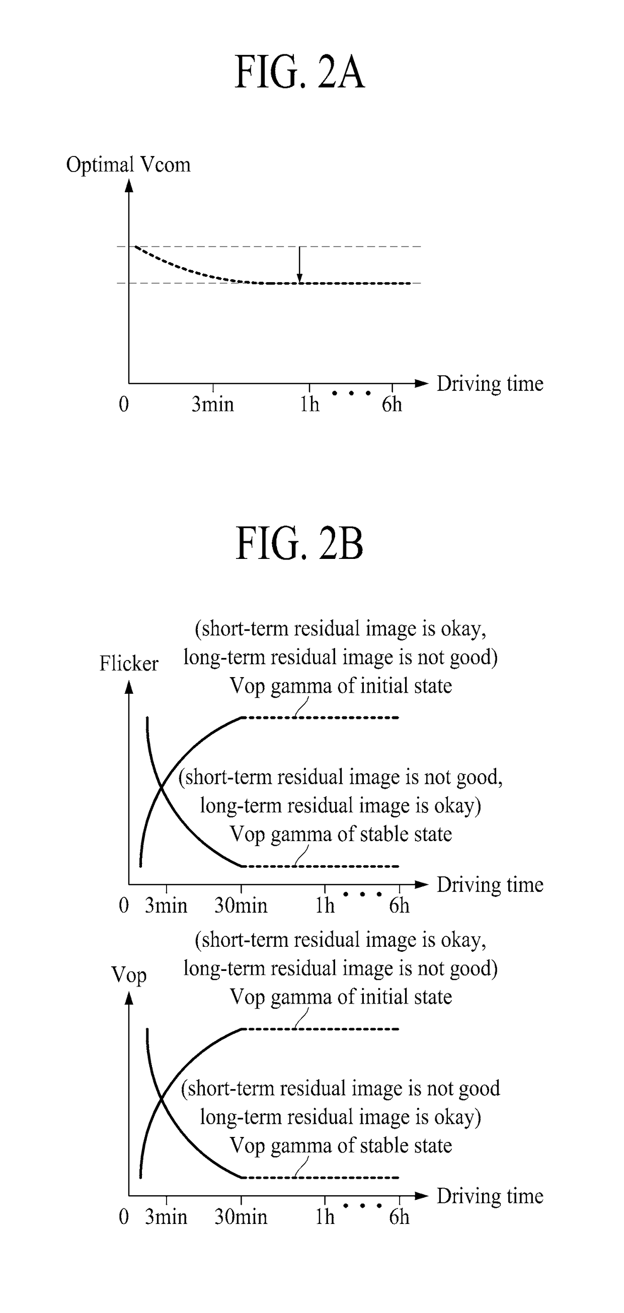
The present invention relates to a liquid crystal display device and a method for driving it. The technical effects of this invention include adjusting the common voltage and gamma voltage based on the operation time to reduce or remove residual images of the initial state or stable state. Additionally, adjusting these voltages based on the operation time may also reduce the final test time and manufacturing cost and enhance manufacturing efficiency. Furthermore, other features and advantages may be set forth through the embodiments of this invention.

Problems solved by technology

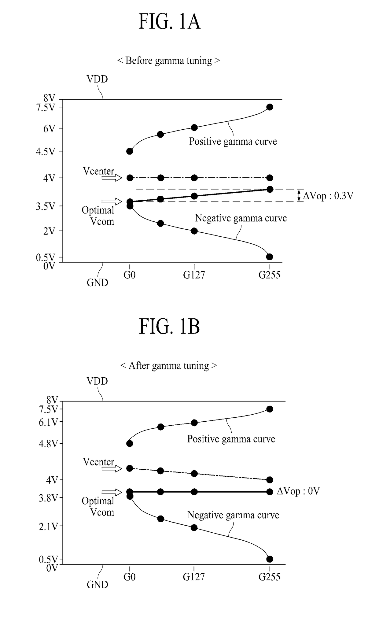
However, in the real driving environment, there is a problem of flicker and residual image phenomenon because of the various reasons such as electrical resistance, parasitic capacitance and thermal stress of the liquid crystal panel when the common voltage is identical to the center voltage.
Therefore, even though the non-uniform optimal common voltages (Optimal Vcom) for each gray level are evaluated, the non-uniform optimal common voltages cannot be applied to the related art liquid crystal display device.
Thus, the image quality is deteriorated.

Method used


Image

  • Liquid crystal panel, liquid crystal display device, and method for driving same
  • Liquid crystal panel, liquid crystal display device, and method for driving same
  • Liquid crystal panel, liquid crystal display device, and method for driving same

Examples


Embodiment Construction

[0048]Hereinafter, a liquid crystal display device and a method for driving the same according to the present invention will be described in detail with reference to the accompanying drawings. Wherever possible, the same reference numbers will be used throughout the drawings to refer to the same or like parts. In the following description, if detailed description of elements or functions known in respect of the present invention is determined to make the subject matter of the present invention unnecessarily obscure, the detailed description may be omitted.

[0049]Advantages and features of the present invention, and implementation methods thereof will be clarified through following embodiments described with reference to the accompanying drawings. The present invention may, however, be embodied in different forms and should not be construed as limited to the embodiments set forth herein. Rather, these embodiments are provided so that this disclosure will be thorough and complete, and ...


PUM


Abstract

The present invention relates to a liquid crystal display (LCD) device which is capable of improving picture quality by switching an optimal gamma voltage and an optimal common voltage on a basis of an operation time, and a method for driving the same. The liquid crystal display device includes a timing controller, a voltage generating unit, a data driver, and a liquid crystal panel. The timing controller can generate voltage control signal for switching initial state to stable state by using certain switching point. The voltage generating unit can receive the voltage control signal, supply the first gamma voltage and the first common voltage during the initial state, and supply the second gamma voltage and the second common voltage during the stable state. The data driver can receive the first gamma voltage in the initial state and the second gamma voltage in the stable state. The liquid crystal panel can suppress short-term residual image if the first gamma voltage and the first common voltage are supplied, and can suppress long-term residual image if the second gamma voltage and the second common voltage are supplied.

Description

TECHNICAL FIELD[0001]The present invention is related to a liquid crystal panel, a liquid crystal display device and a method for driving the same, in which display quality can be improved by switching a common voltage and a gamma voltage on the basis of an operation time.BACKGROUND ART[0002]Owing to a technological development for mass production, an easy driving means, a low power consumption, a high picture quality and a realization of large screen, a liquid crystal display (LCD) device is appropriate for a portable device, and furthermore its application field has gradually increased.[0003]According to a method for controlling an alignment of a liquid crystal layer in the LCD device, the LCD device may be developed in various modes, for example, Twisted Nematic (TN) mode, Vertical Alignment (VA) mode, In-Plane Switching (IPS) mode, Fringe Filed Switching (FFS) mode, etc.[0004]In case of the IPS mode, both a pixel electrode and a common electrode are alternately arranged in horiz...

Claims


Application Information

Patent Timeline
Patent Type & Authority Applications(United States)
IPC IPC(8): G09G3/20G09G3/36
CPCG09G3/2007G09G3/3648G09G2320/0247G09G2320/0257G09G2320/0276G09G2320/048G09G2310/08G09G2320/0673G09G2300/0434
Inventor PARK, SUN KYU
Owner LG DISPLAY CO LTD
Learn More