
Light-field Imaging Using a Gradient Metasurface Optical Element

a metasurface and optical element technology, applied in the field of lightfield imaging, can solve the problems of reducing the spatial resolution compared to a conventional microscope, the spatial resolution of reconstructions using deconvolution algorithms is not uniform across their depth, and it is extremely difficult to create the phase mask on each lenslet using conventional optics techniques

Active Publication Date: 2017-05-25
THE BOARD OF TRUSTEES OF THE LELAND STANFORD JUNIOR UNIV
View PDF2 Cites 50 Cited by
  • Summary
  • Abstract
  • Description
  • Claims
  • Application Information

AI Technical Summary

Benefits of technology

The patent describes a new type of light imaging system that uses a metalens array made of special optical elements. These elements are arranged in a way that allows the system to capture images with high resolution. The system includes multiple sub-elements, each with different functions and optical properties. The sub-elements can be encoded with different spatial patterns, and work together to manipulate various states of polarization. The metalens array is combined with at least one tube lens to project images onto a focal plane. The technical effects of this system include improved image quality and a compact design.

Problems solved by technology

In these traditional systems, both the lateral and axial information of an object can be recorded simultaneously, but there is an inherent trade-off between the lateral and axial resolutions.
For example, conventional light-field microscopy can image large volumes at high speed but suffers from a decreased spatial resolution compared to a conventional microscope.
However, the spatial resolutions of the reconstructions using the deconvolution algorithms have been shown to be non-uniform across their depth.
However, the superior performance of this approach has been demonstrated only in simulation because it is extremely challenging to create the phase mask on each lenslet using conventional optics techniques.
However, this approach can probe only the image information on a limited number of discrete planes and does not capture the true 4D light fields.
In addition to being ultrathin and compact, these multifunctional metasurfaces can provide entirely new functions that are very difficult or impossible to be achieved with conventional optical components.

Method used


Image

  • Light-field Imaging Using a Gradient Metasurface Optical Element
  • Light-field Imaging Using a Gradient Metasurface Optical Element
  • Light-field Imaging Using a Gradient Metasurface Optical Element

Examples


Embodiment Construction

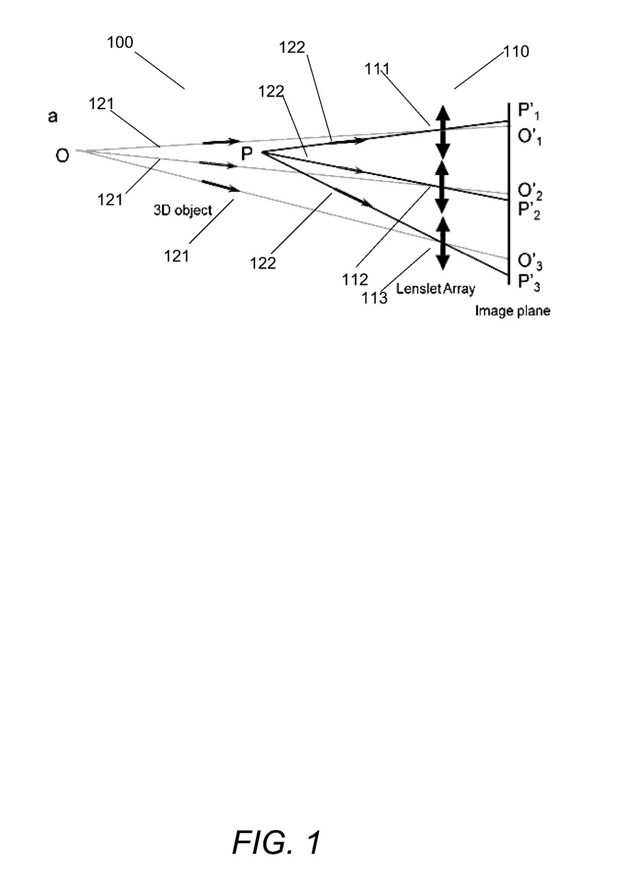
[0035]Turning now to the drawings, various embodiments of systems and methods that perform light field imaging using gradient metasurface optical elements are disclosed. The multiplexed metalens array is provided by a gradient metasurface optical element in accordance with some embodiments of the invention. The multiplexed metalens array includes multiple interleaved sub-elements. Each of the sub-elements may have different optical functionalities in accordance with many embodiments of the invention. In accordance with some of these embodiments, a phase profile of multiplexed metalens array is a spatial multiplexing of the phase profile of N sub-elements where N is the number of sub-elements.

[0036]In accordance with some embodiments, each of the N sub-elements included in the multiplexed metalens array have a different optical axis. Thus, each of the N sub-elements can capture the information from different perspectives. In accordance with many embodiments, the N sub-elements with p...


PUM


Abstract

Embodiments of 3D imaging systems that use a multifunctional, nano structured metalens to replace the conventional microlens array in light field imaging are disclosed. The optical focusing properties of the metalenses provided by gradient metasurface optical elements. The gradient metasurfaces allow the properties of the elements of the metalens array to be changed by tuning the gradient metasurfaces.

Description

CROSS-REFERENCE TO RELATED APPLICATIONS[0001]The current application claims priority to U.S. Provisional Patent Application No. 62 / 258,364, filed Nov. 20, 2015 and U.S. Provisional Patent Application No. 62 / 286,911 filed Jan. 25, 2016, the disclosures of which are incorporated herein by reference as if set forth herein in their entirety.FIELD OF THE INVENTION[0002]This invention relates to light-field imaging and more particularly to light-field imaging using gradient metasurface microlenses.BACKGROUND OF THE INVENTION[0003]Light-field imaging has attracted wide attention because of its ability to achieve simultaneous three-dimensional (3D) imaging by capturing projections of four-dimensional (4D) light fields and using the 4D light fields to reconstruct 3D volumes as explained in more detail in Levoy, M., Ng, R., Adams, A., Footer, M. & Horowitz, M. Light field microscopy. ACM Trans. Graph. 25, 924 (2006). Traditional light-field imaging systems use arrays of spatially separated mi...

Claims


Application Information

Patent Timeline
Patent Type & Authority Applications(United States)
IPC IPC(8): G02B27/22H04N13/02G02B5/00G02B13/00G02B1/00G02B3/00
CPCG02B27/2214G02B1/002H04N13/0203G02B5/008G02B13/0095G02B3/0056G02B21/004G02B21/361G02B21/367H04N13/204G02B3/0068G02B3/0043G02B3/0062G02B1/007
Inventor LIN, DIANMINBRONGERSMA, MARK L.KIK, PIETER G.WETZSTEIN, GORDON
Owner THE BOARD OF TRUSTEES OF THE LELAND STANFORD JUNIOR UNIV
Learn More