Construction machine

Active Publication Date: 2017-05-25
KOBELCO CONSTR MASCH CO LTD
View PDF2 Cites 4 Cited by
  • Summary
  • Abstract
  • Description
  • Claims
  • Application Information

AI Technical Summary

Benefits of technology

The present invention relates to a construction machine that can prevent the injection unit from getting overheated and causing a risk of failure. This prevents the engine from stopping while the injection unit is in a high-temperature state, reducing the risk of failure of the injection unit.

Problems solved by technology

With an SCR apparatus, there is a problem in that, when an engine is stopped by turning off an ignition key or the like, a temperature of a dosing valve rises due to residual exhaust gas in an exhaust tube and causes urea water to deteriorate in the dosing valve.
However, in Japanese Unexamined Patent Publication No. 2012-17687, since urea water is injected after the engine is stopped, there is a problem in that water content in the urea water evaporates and urea is deposited, and the deposited urea crystallizes and adheres to an exhaust tube or the like to cause clogging of the exhaust tube.
Since Japanese Patent No. 5562503 adopts “150” as the first prescribed value and the injection apparatus is repeatedly exposed to a high-temperature environment, there is a problem in that the injection apparatus cannot be sufficiently protected.
In addition, since the cooling time is not calculated in Japanese Unexamined Patent Publication No. 2012-17687, an operator has no idea how long an idle time must continue before turning off the engine.
Japanese Patent No. 5562503 has another problem in that, since the engine is turned off without the injection apparatus having been sufficiently cooled, the injection apparatus cannot be sufficiently protected.

Method used


Image

  • Construction machine
  • Construction machine
  • Construction machine

Examples


first embodiment

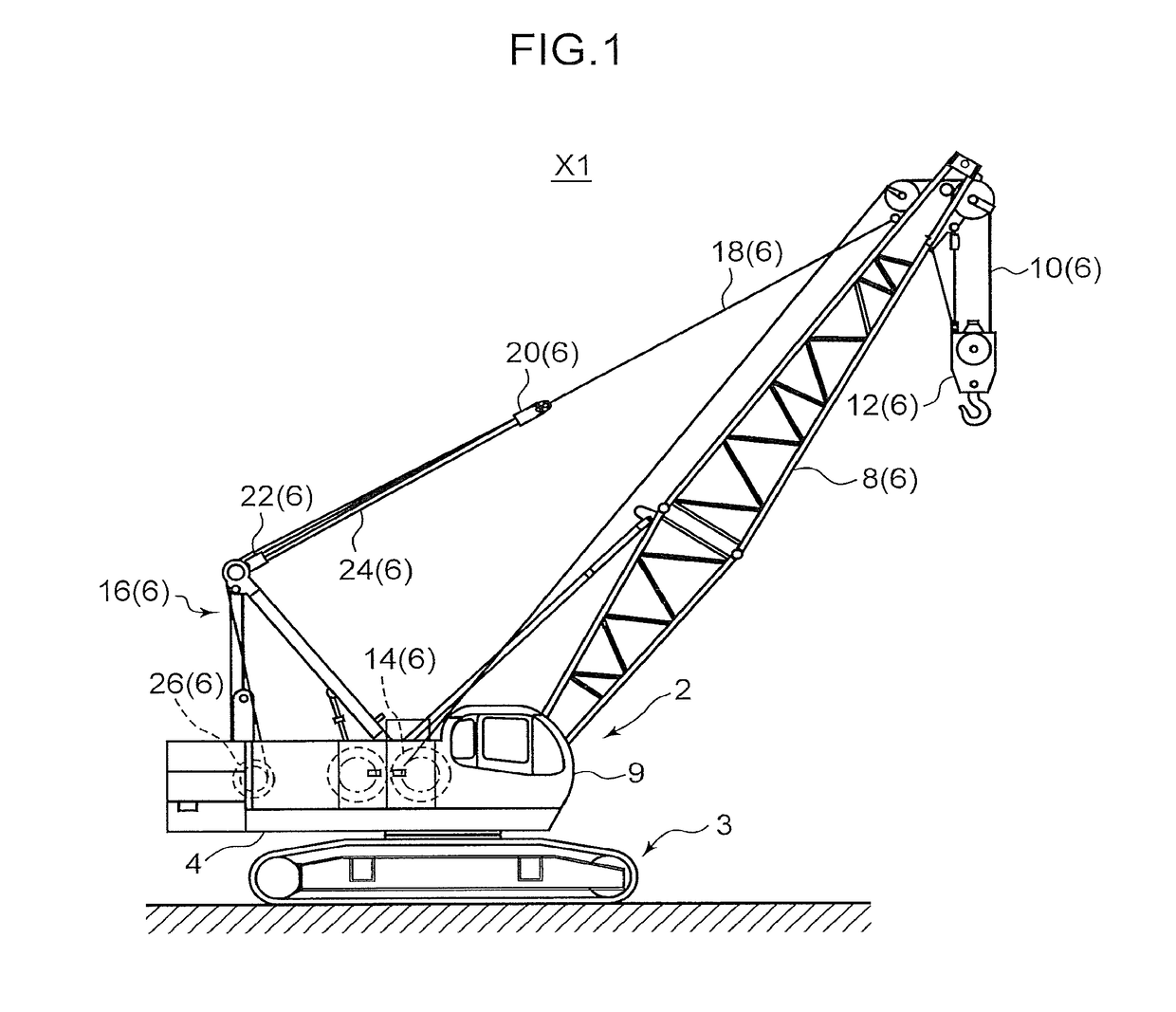
[0044]FIG. 1 is an external view of a crawler crane X1 in a case where a construction machine according to an embodiment of the present invention is applied to the crawler crane X1. While a description of an example of the crawler crane X1 will be presented below, the present invention is not limited thereto and is applicable to a wheel crane, an excavator, and other construction machines equipped with an exhaust purification function. As shown in FIG. 1, the crawler crane X1 includes an upper rotating body 2 and a lower traveling body 3.

[0045]The upper rotating body 2 includes a revolving frame 4 and a work apparatus 6 mounted on top of the revolving frame 4. The work apparatus 6 is used for performing suspending work (a crane operation) with respect to a suspended load. Specifically, the work apparatus 6 includes a boom 8, a lifting rope 10, a hook apparatus 12, a lifting winch 14, a gantry 16, a guy-line 18, an upper spreader 20, a lower spreader 22, a hoisting rope 24, and a hoi...

second embodiment

[0111]The crawler crane X1 according to a second embodiment differs from that of the first embodiment in a condition applied when decrementing the cooling time CT. Moreover, in the present embodiment, same components as the first embodiment will be denoted by same reference numerals and a description thereof will be omitted.

[0112]A difference between the second embodiment and the first embodiment is represented in the flow chart shown in FIG. 4. FIG. 6 is a flow chart showing an example of processing of the crawler crane X1 according to the second embodiment of the present invention. In FIG. 6, compared with FIG. 4, a process of S601 has been added while the processes of S416 and S418 have been deleted. In addition, in FIG. 6, since S415 differs from that shown in FIG. 4 due to S601 being provided, a reference character “a” is appended.

[0113]When the exhaust temperature ET is not higher than 250 degrees (NO in S401) and neither an accelerator operation nor a lever operation has been...


PUM


Abstract

A cooling time computing unit computes, based on a temperature detected by a temperature detection unit, a cooling time during which an injection unit is cooled by driving of an engine. A notification control unit uses a notification unit to notify an operator of a necessity of cooling before the engine is stopped, during the cooling time computed by the cooling time computing unit.

Description

BACKGROUND OF THE INVENTION AND RELATED ART STATEMENT[0001]Technical Field[0002]The present invention relates to a construction machine equipped with an exhaust purification function.[0003]Background Art[0004]A selective catalystic reduction (SCR) apparatus is an example of apparatuses for purifying NOx in exhaust gas of a diesel engine.[0005]With an SCR apparatus, there is a problem in that, when an engine is stopped by turning off an ignition key or the like, a temperature of a dosing valve rises due to residual exhaust gas in an exhaust tube and causes urea water to deteriorate in the dosing valve. In consideration thereof, Japanese Unexamined Patent Publication No. 2012-17687 discloses a technique involving, based on exhaust gas temperature when an engine is stopped, setting a cooling time required for a temperature of a dosing valve to drop to a temperature at which urea water is less likely to deteriorate, and injecting urea water from the dosing valve until the cooling time l...

Claims


Application Information

Patent Timeline
IPC IPC(8): F02D41/02B66C13/16B66C13/54F02D41/04F01N3/20F01N11/00F01N3/02B66C13/18B66C15/06
CPCF02D41/0235B66C13/18B66C13/16B66C13/54B66C15/06F02D2041/0265F01N11/002F01N3/02F02D41/042B66C23/36F01N3/206F01N3/2066F01N2560/06F01N2590/08F01N2610/02F01N2610/11F01N2900/08F01N2900/1602F02D2200/0802Y02T10/12Y02T10/40
Inventor TSURUMI, TOSHIKIKIMITANI, TSUKASATERASAKA, JOJISASAI, SHINTAROH
Owner KOBELCO CONSTR MASCH CO LTD
Why Eureka
Try Eureka