Torrefaction/Gassification System

a technology of gassification system and turbine, which is applied in the direction of biofuels, fuels, waste based fuels, etc., can solve the problems of syngas entering the facility, affecting the safety of workers, so as to limit the possibility of syngas leakage

Active Publication Date: 2017-05-25
CEG TECH UK LTD
View PDF4 Cites 1 Cited by
  • Summary
  • Abstract
  • Description
  • Claims
  • Application Information

AI Technical Summary

Benefits of technology

The patent text describes a process to make the torrefaction process safer by reducing the potential for syngas leakage and explosions. The technical effects of this process include sealing off excess ventilation ports, reducing the number of conduits, and using a single syngas bleed to power a gas engine. Additionally, the use of non-volatile exhaust gas from the gas engine and the injection of cold air into the exhaust gas stream helps prevent thermal runaway and minimizes the risk of fires and explosions. Furthermore, sealing off the reactor from the bottom chamber allows for higher flue gas temperatures without compromising the structural integrity of the reactor.

Problems solved by technology

At these higher temperatures with syngas one creates a massive safety risk such that any leak is going to involve a flammable hot gas that is looking for oxygen.
Because of the vibration the aforementioned glands have ruptured and many leaks and fires have been caused at the facility in which the Carrier dryers have been modified with conventional flexible connections.
Originally the flexible connections were made out of fabric but the fabric could not handle the temperatures and would eventually rupture and result in leaks.
However, the vibration in and of itself loosened these glands and with as many as 15 of these metal connections if any one of them leaks it puts syngas into the facility and is an ever present risk.
Also because syngas is predominantly carbon monoxide, health and safety of the employees in such a plant are also a significant risk.
It is noted that prior torrefaction plants have exhibited an average 50-60% thermal efficiency in part because the amount of evolved syngas cannot be adequately controlled and the excess heat generated is lost.
The problem with respect to thermal runaway is that when wood is torrefied at 250° C. to 300° C. about 40 percent of the thermal energy within the wood when torrefying wood is volatile at these temperatures and managing the process so that only 20% is evolved is an exacting control issue requiring razor sharp response time and also the ability to both add and remove heat from the process.
One wants to utilize only 20 percent of the heat, because anything more would be wasted.
If one cannot soak up the remaining 20 percent of the torrefaction heat generated, the process tends to want to run away.
This in turn makes most torrefaction processes very inefficient.
It is also this inability to utilize the heat that is generated in the process which causes thermal runaway that leads to high reactor temperatures, fires and a large number of other safety concerns.
The reason this is a problem is because the generator usually has a fixed maximum capacity of, for instance 560 kilowatts, and one runs the risk of actually running out of capacity in the generator.
If one wants to run the generator flat out all the time one can reach the maximum capacity of the generator which in turn limits the amount of energy that can be withdrawn from the system.
Thus, the maximum capacity of the generator limits the amount of energy that can be taken out.
That would be too far.
It is noted that even when using a single pipe one does not want to operate that pipe at very high pressure because it will create a leak which will be a health and fire safety concern.
However one cannot mix cold air with syngas as it would combust or potentially explode.
The problem with the oxidizer is that it simply produces far more heat than the process needs.

Method used


Image

  • Torrefaction/Gassification System
  • Torrefaction/Gassification System
  • Torrefaction/Gassification System

Examples


Embodiment Construction

Prior Art

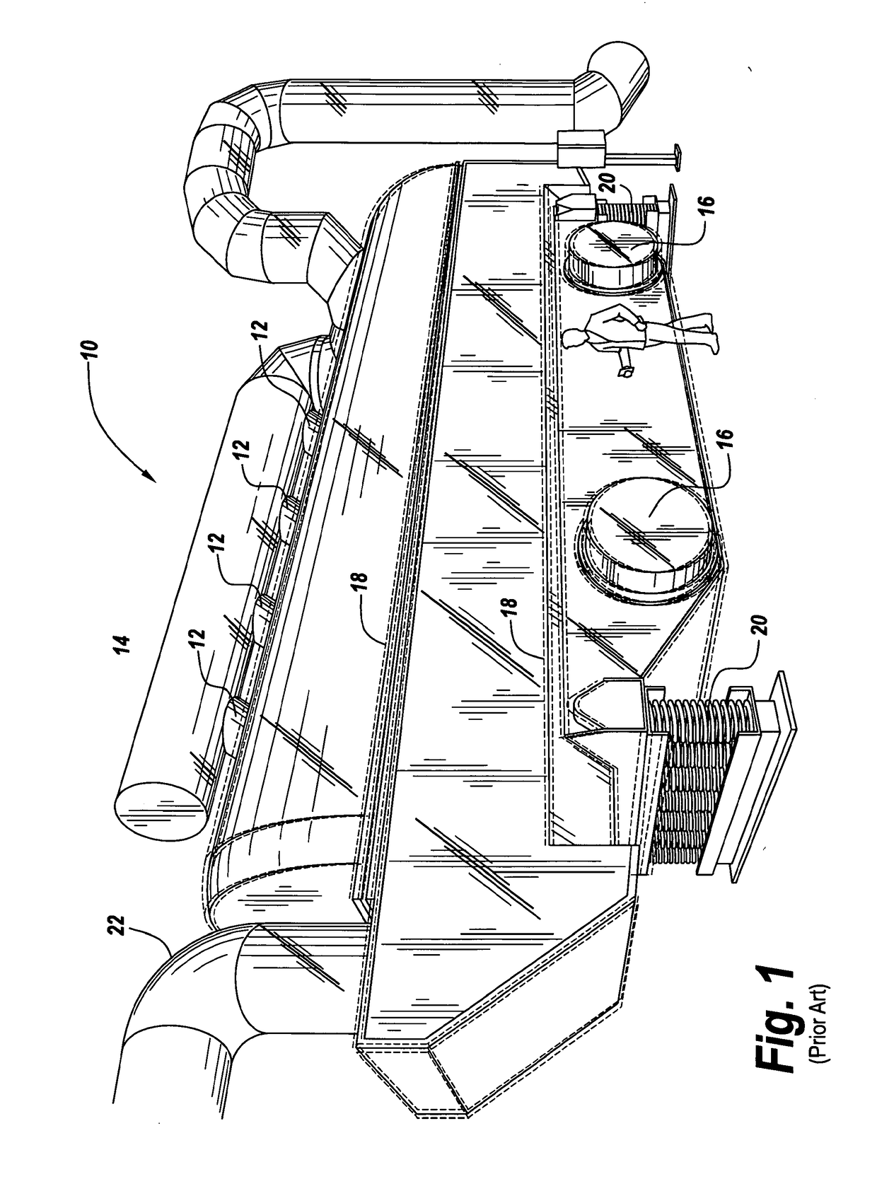
[0033]Referring now to FIG. 1, a reactor 10 in the form of a modified Carrier vibratory dryer includes syngas ducting conduits 12 which are coupled to a manifold 14 for capturing the syngas generated by the reactor. As illustrated, off center weights in modules 16 cause the entire reactor to vibrate as illustrated by the dotted lines 18, with reactor mounted on springs 20 to permit the vibrating. Here the biomass is introduced at duct work 22 so that it travels down the interior of the reactor to produce biocoal.

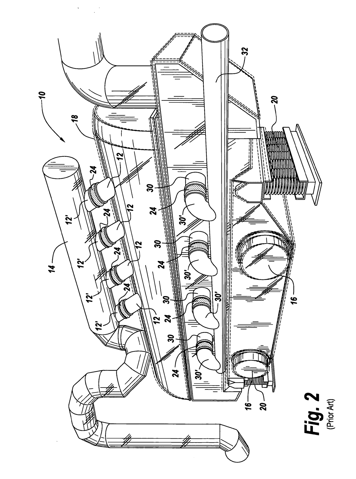
[0034]Referring to FIG. 2, the other side of reactor 10 is shown in which duct work 12 is shown coupled to the aforementioned manifold 14, with the joints between the duct work and the portions of the conduit 12′ joined through the utilization of a gland 24 which permits movement between conduits 12 and 12′ with the motion 18 of reactor 10 and manifold 14. Also shown are inlet conduits 30 which have glands 24 interposed between conduits 30 and the exterior portions ...


PUM

PropertyMeasurementUnit
temperaturesaaaaaaaaaa

Abstract

A modified dryer operates on a different principle from that used by the prior torrefaction plants. The subject invention utilizes thermal conduction to torrefy the biomass in a vibratory reactor in which a heated solid unperforated plate is sealed in the reactor to separate the biomass above from the gas used to heat the plate below. This permits using inert flue gas to heat the reactor which in turn permits the use of a cool air damping system to prevent thermal runaway. Also syngas evolved from the process is utilized to power a gas engine, the exhaust output of which is recirculated to heat the reactor plate. When the gas engine is coupled to an electric generator, waste energy is recovered for use in other parts of the plant or exported elsewhere.

Description

CROSS REFERENCE TO RELATED APPLICATION[0001]This application is a divisional of U.S. patent application Ser. No. 13 / 998,761, filed on Dec. 3, 2013, the entire disclosure of which are incorporated herein by reference.FIELD OF THE INVENTION[0002]This invention relates to torrefaction systems and more particularly to an environmentally safe fire and explosion resistant system in which a standard commercial vibratory dryer is modified to provide a reactor.BACKGROUND OF THE INVENTION[0003]Torrefaction, or the roasting of a biomass such as wood chips and the like, has been used in the past to produce biocoal, which is packaged as a briquette or pellet that can be utilized to replace fossil fuel. The biocoal is characterized by high energy density, homogeneity, is hydrophobic, exhibits no biologic activity and offers improved grindability, making the torrefied product not only coming from a sustainable source such as renewable wood supplies but also is environmentally sound, oftentimes whe...

Claims


Application Information

Patent Timeline
Patent Type & Authority Applications(United States)
IPC IPC(8): C10L9/08C10L5/44
CPCC10L9/083C10L2290/08C10L2290/06C10L5/447Y10T29/49716Y02E50/10Y02E50/30
Inventor BALON, JR., THOMASBUTLER, NEIL
Owner CEG TECH UK LTD
Why Eureka
Try Eureka