
Adjusting device for a safety belt with an extendable belt guiding element

a technology of adjusting device and safety belt, which is applied in the direction of vehicle safety belts, vehicle components, vehicle arrangements, etc., can solve the problems of not providing any further possibility of adjusting the positioning of the belt, and requiring a relatively large amount of constructional space. , to achieve the effect of fastening the safety belt of a vehicle occupant and little constructional spa

Active Publication Date: 2017-05-11
BROSE FAHRZEUGTEILE GMBH & CO KG
View PDF0 Cites 3 Cited by
  • Summary
  • Abstract
  • Description
  • Claims
  • Application Information

AI Technical Summary

Benefits of technology

The present invention relates to an improved adjusting device for a belt extender in a vehicle. The device can facilitate the fastening of the safety belt and also adapt the position of the belt guiding element after the occupant has fastened the belt. The device requires a minimal amount of space and can be accommodated in the B-pillar of a motor vehicle. In one embodiment, the belt guiding element also serves to guide the safety belt in the region of the shoulder of the occupant. The device has a flexible supporting element that can be adjusted in both directions and can be actuated by an external force to move the belt guiding element. The links of a chain have limited movement and can hold the belt guiding element securely. The adjusting device can be electronically controlled and can be extended by an external force.

Problems solved by technology

The adjusting device proposed in DE 10 2004 036 189 A1 requires a relatively large amount of constructional space and is not suitable for arranging on a B-pillar of a motor vehicle.
Additionally, the adjusting device disclosed in DE 10 2004 036 189 A1 does not provide any possibility of adjusting a position of the belt guiding element after a vehicle occupant has fastened the safety belt.
Accordingly, DE 10 2009 009 906 A1 also does not provide any further possibility of adjusting the positioning of a belt guiding element.

Method used


Image

  • Adjusting device for a safety belt with an extendable belt guiding element
  • Adjusting device for a safety belt with an extendable belt guiding element
  • Adjusting device for a safety belt with an extendable belt guiding element

Examples


Embodiment Construction

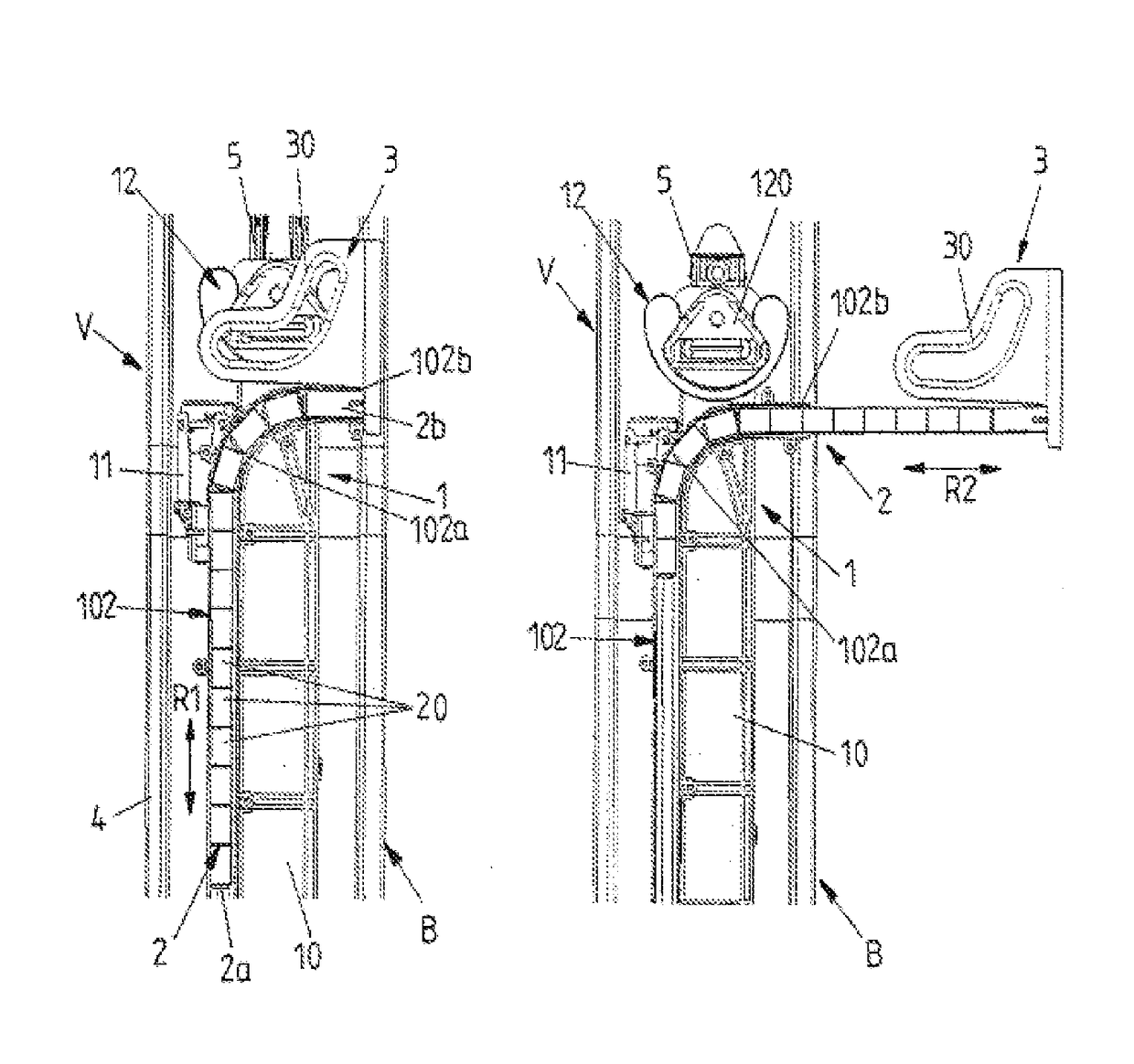
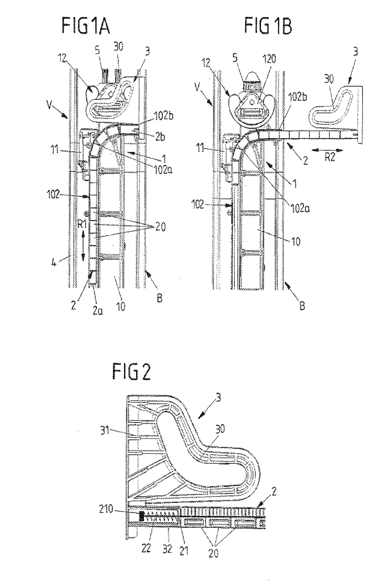
[0046]An adjusting device V according to the invention which is accommodated on a B-pillar B of a motor vehicle is shown in FIGS. 1A and 1B. FIGS. 1A and 1B in this case show the B-pillar B in side view with a view of the vehicle interior and without the cladding conventionally fixed thereto.

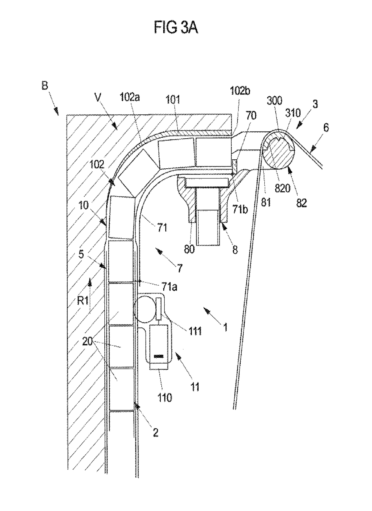
[0047]The adjusting device V comprises a belt guiding subassembly 1 for a safety belt of a vehicle seat. A portion of the safety belt, which is not shown in FIGS. 1A and 1B for reasons of clarity, is guided along the B-pillar B via the belt guiding subassembly 1. The belt guiding subassembly 1 in this case comprises, in particular, an adjusting part 10 which is able to be adjusted in the longitudinal direction of extent of the B-pillar B, and a belt guiding element 12 fixed to the adjusting part at the upper end of the adjusting part 10. A belt outlet opening 120 is defined via the belt guiding element 12, the safety belt being guided through said belt outlet opening, from the inside of the holl...


PUM


Abstract

An adjusting device for a safety belt in a vehicle comprises at least one extendable belt guiding element which is provided for guiding a portion of the safety belt and at least one supporting element which is connected to the belt guiding element and which is able to be at least partially extended together with the belt guiding element. The belt guiding element is able to be extended from a resting position in a direction of extension in order to facilitate the grasping of the safety belt by a vehicle occupant when fastening the safety belt. The supporting element is flexible but in the extended state of the belt guiding element is sufficiently rigid at least in one portion transversely to the direction of extension such that the belt guiding element is held in an extended position via the now rigid portion of the supporting element.

Description

CROSS-REFERENCE TO A RELATED APPLICATION[0001]This application is a National Phase Patent Application of International Patent Application Number PCT / EP2015 / 057857, filed on Apr. 10, 2015, which claims priority of German Patent Application Number 10 2014 207 036.8, filed on Apr. 11, 2014, the entire contents of all of which are hereby incorporated by reference.BACKGROUND[0002]The present invention relates to an adjusting device for a safety belt in a vehicle.[0003]Such an adjusting device comprises at least one belt guiding element which is provided for the guidance of a portion of the safety belt. The belt guiding element in this case is designed to be extendable in order to facilitate the grasping of the safety belt, for example on an insertion tongue for a belt buckle, by a vehicle occupant when fastening the safety belt. The adjusting device may be designed, therefore, as a so-called belt extender in order to displace to the front a portion of the safety belt to be grasped by a v...

Claims


Application Information

Patent Timeline
IPC IPC(8): B60R22/20B60N2/90
CPCB60R22/20B60R2022/207B60R2022/1818B60R22/03B60R2022/208
Inventor STEGERER, MARIOHOEPPEL, MICHAELBAUERNFEIND, MARKUS
Owner BROSE FAHRZEUGTEILE GMBH & CO KG
Learn More