Model airplane
- Summary
- Abstract
- Description
- Claims
- Application Information
AI Technical Summary
Benefits of technology
Problems solved by technology
Method used
Image
Examples
example 1
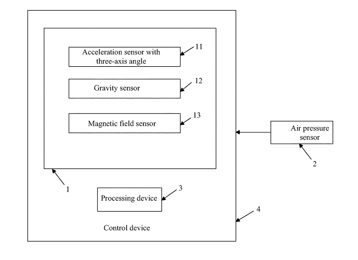
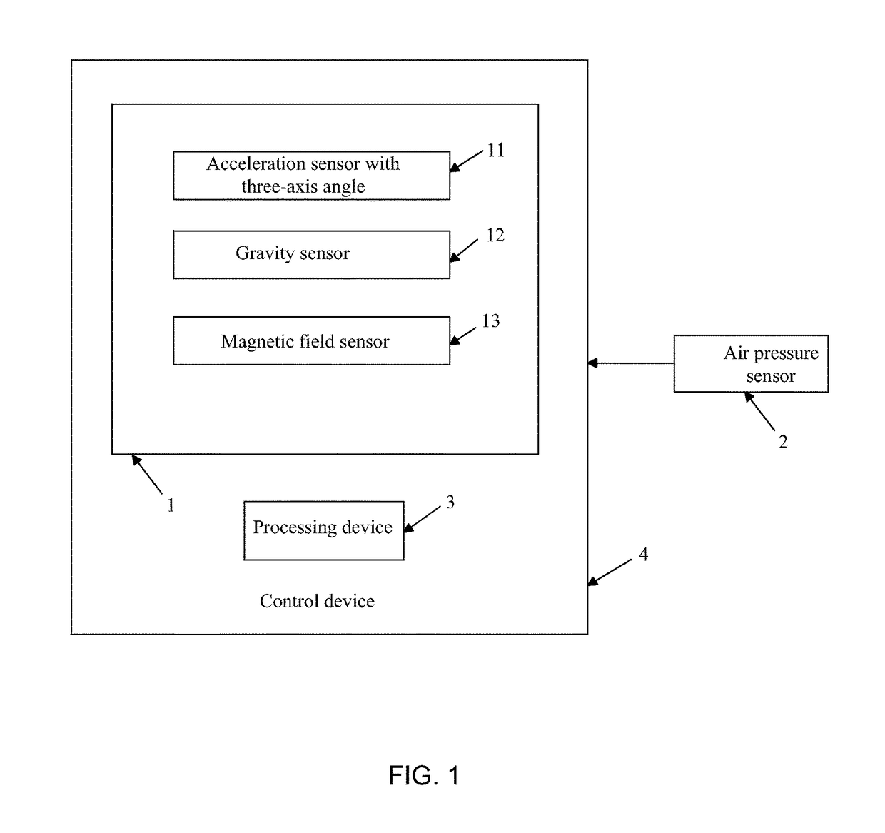
[0047]As shown in FIG. 1, the model airplane in this example contains a detection device 1 which is in the gravity center of the model airplane, an air pressure sensor 2 which is on the belly of the model airplane, processing device 3 and control device 4. The detection device 1 is in the gravity center position, which can detect the flight posture, course data and other various flight data for the model airplane more accurately. Thereinto, the detection device 1 includes an acceleration sensor with three-axis angle 11, gravity sensor 12 and magnetic field sensor 13. The acceleration sensor with three-axis angle 11 can detect the angular acceleration of the model airplane in real time, and send angular acceleration to the processing device 3. Further, the processing device 3 can, based on the angular acceleration, work out the rotation angle of the model airplane in the direction of each coordinate axis; the gravity sensor 12 can timely detect gravity acceleration with three-axis of...
example 2
[0056]As shown in FIG. 1, the model airplane in this example contains a detection device 1 which is in the gravity center of model airplane, an air pressure sensor 2 which is in the model airplane belly, the processing device 3 and the control device 4.
[0057]The difference between this example and example 1 is: in this example, the control signal transmitted by the control device 4 can be used to make the model airplane fly through maintaining a fixed flight posture. It can be set as the various modes when the model airplane is flying specifically. For example, the model airplane can be set to find the upflow automatically, and then maintain a fixed flight posture to climb step by step; it can be also set to automatically adjust to the initial state of some acrobatic maneuvers when the model airplane is flying in the sky. In this way, users can concentrate on practicing the fixed acrobatic maneuvers to study flight skills of the model airplane deeply.
example 3
[0058]As shown in FIG. 1, the model airplane in this example also contains a detection device 1 which is in the gravity center of model airplane, a air pressure sensor 2 which is in the model airplane belly, the processing device 3 and the control device 4.
[0059]The difference between this example and example 1 is: in this example, the control device 4 can detect the received flight altitude, when the flight altitude of the control device 4 is smaller than or equal to first altitude threshold through detection, the protection mode is used to make the model airplane fly in the first condition; when the flight altitude of the control device 4 is larger than the first altitude threshold, and smaller than the second altitude threshold through detection, the protection mode is used to make the model airplane fly in the second condition; when the flight altitude of the control device 4 is higher than the second altitude threshold through detection, the protection mode is used to make the ...
PUM
 Abstract
Description
Claims
Application Information
 - R&D
- Intellectual Property
- Life Sciences
- Materials
- Tech Scout
- Unparalleled Data Quality
- Higher Quality Content
- 60% Fewer Hallucinations
Browse by: Latest US Patents, China's latest patents, Technical Efficacy Thesaurus, Application Domain, Technology Topic, Popular Technical Reports.
© 2025 PatSnap. All rights reserved.Legal|Privacy policy|Modern Slavery Act Transparency Statement|Sitemap|About US| Contact US: help@patsnap.com


