
High-speed hydraulic forming of metal and non-metal sheets using electromagnetic fields

a technology of electromagnetic fields and metal and non-metal sheets, which is applied in the direction of presses, manufacturing tools, presses, etc., can solve the problems of low formability, inability to use conventional forming methods to form these high-strength metals, and metals which are typically used in sheet form, so as to prevent fluid backflow, prevent fluid backflow, and prevent fluid backflow

Inactive Publication Date: 2017-04-06
NIARAKI RASOUL JELOKHANI +2
View PDF6 Cites 18 Cited by
  • Summary
  • Abstract
  • Description
  • Claims
  • Application Information

AI Technical Summary

Benefits of technology

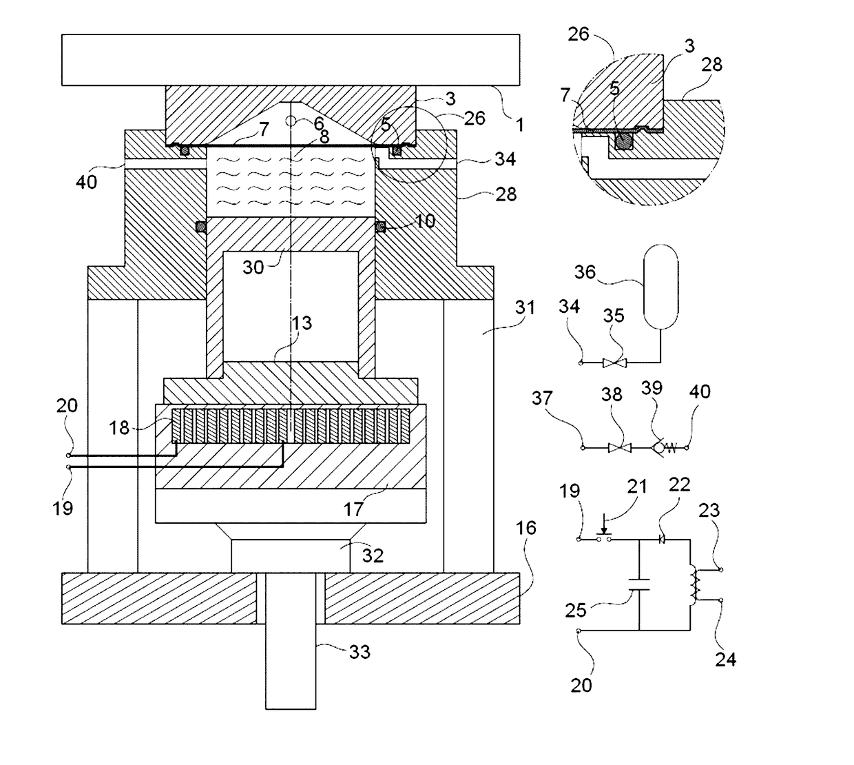
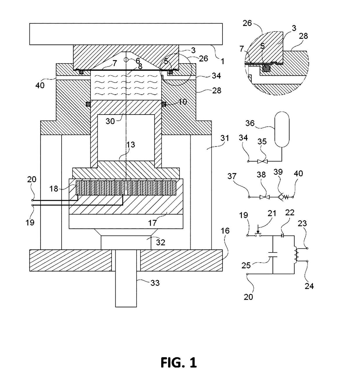
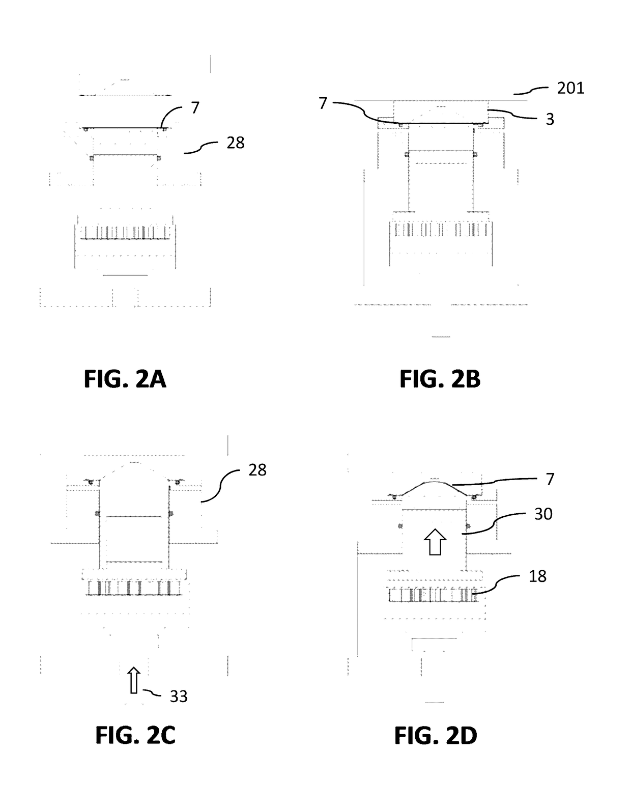
The patent describes a system and method for high-speed forming of metal and non-metal sheets using electromagnetic fields. The system includes a coil connected to a power generator, a conductive plate, a pressure chamber, a piston, a material sheet, a rubber pad, and a die. The method involves creating a first electromagnetic field in the coil, placing a conductive plate on top of the first field to create a second electromagnetic field in the opposite direction, and using the second field to push the conductive plate away from the coil. The force is transferred to the fluid inside the pressure chamber, which then pushes the material sheet to take the shape of the die. The technical effects of the system and method include high-speed forming of sheets, improved accuracy of forming, and reduced air bubbles in the sheet.

Problems solved by technology

However, such metals which are typically used in sheet form, have low formability.
Therefore, conventional forming methods cannot be used for forming these high strength metals.
Recent studies show that high-speed forming methods can cause an increase in the strain rate of the metal sheets and therefore can increase their formability.
However, each of the methods have drawbacks.
For example, the explosive forming method cannot be automated.
The electromagnetic forming requires the metal sheet to have high conductivity and as such the electromagnetic method cannot be applied to non-conductive material.
These high strength materials have low formability and special forming method is needed to form sheets of the material into desired shapes.
However, each of the methods has multiple drawbacks.
The electric energy can evaporate the water between the two electrodes and the pressure from the shock wave produced from the steam can increase rapidly and cause a shock in the fluid (water).
For example, the explosive forming method cannot be automated.
The explosive method requires an explosive storage which can be unsafe and costly.
In addition, the energy produced from explosion cannot be easily adjusted and therefore, the forming may not have a high precision.
The electromagnetic method cannot be applied to non-conductive material.
However, the driver sheet cannot be reused.
In addition, in electromagnetic method due to the distance between coil rings the electromagnetic field produced in the coil may not be uniform.
Moreover, the electromagnetic forming process cannot be performed in multiple steps.
In addition, because heat is produced in the formed part during the electromagnetic forming due to the electric current, electromagnetic method cannot be used for forming thin heat sensitive sheets.
In the electromagnetic forming, using a large coil for a small sheet may cause the electrical energy discharged from the capacitors to go waste.
In addition, electromagnetic method cannot be used for forming sheets made of two or more materials with different conductivities.
This process is time consuming.
In the electrohydraulic forming method, the electrodes are gradually corroded and the distance between electrodes increases due to corrosion.
Corrosion of electrodes can gradually pollute the fluid and the electrical properties of the fluid such as conductivity and the pressure from the shock wave produced within the chamber may change due to pollution.
In electrohydraulic forming, the particles released in the fluid due to electrode corrosion can rapidly hit the formed part in next explosions and cause scratching and damaging to the formed part.
This can cause additional time spent on each forming step.
The distance between the electrodes and the sheet is an important parameter in forming and adjustment of the distance is a hard and time consuming process.
In electrohydraulic forming with multiple steps, the distance between the fixed electrodes and the sheet increases at each step of the process and as a result later steps of the forming process may require higher energy.
In some cases, the forming process may not be completed in one step and multiple steps may be needed.
Any movement in the hydraulic jack 33 at this step may drastically reduce the efficiency of the forming process.
For example, grease or thick oils may contain small amounts of air which if not removed prior to the forming process can cause a waste of energy for compression of (and heating) the air.
If the plate 13 and piston 30 are not tightly fastened together, the pressure may cause a collision between the plate 13 and piston 30 and this can cause energy loss.
Lack of symmetric energy transfer can reduce the life of the system.
The driver sheet cannot be reused and is considered waste product after completion of the forming process.
Using the auxiliary sheet reduces efficiency of forming process by energy loss due to forming of the auxiliary sheet.
It is noted that methods such as electromagnetic forming method do not provide multi-step forming.
In electromagnetic forming, if a large coil is used for forming a small piece, a large part of the produced electric energy gets wasted, because the whole energy cannot be concentrated on the sheet, while in the described system and method it is possible to concentrate the produced energy on the sheet by using a large conducive plate and small piston.
In electromagnetic forming method, forming thin sheets or heat sensitive sheets increased temperature during the process due to the induced eddy current may damage the sheet.
For example, the sheet may melt or get distorted.
The electromagnetic forming method cannot be used for forming parts of the piece in locations distant from the coil.
For example, the electromagnetic forming method cannot be used for expansion forming of narrow pipes.
This is because due to narrow diameter of the pipe, installing a coil inside the pipe may not be possible.
However, in the described system and method the fluid can easily transfer the pressure to the inside part of the narrow pipe and form parts of the piece which are distant from the coil.
However, in the described system and method, forming complex and detailed pieces can be performed with one flat coil without the need for changing the coil.
In electrohydraulic forming method, electrodes are damaged due to corrosion and they need to be replaced with new electrodes periodically.
This increases the process cost.
In electrohydraulic forming method, electrode corrosion gradually pollutes the fluid.
In electrohydraulic forming method, electrode corrosion may spread particles from the electrodes inside the fluid.
These particles, in addition to polluting the fluid, can cause damage to the sheet and the formed piece.
For example, the pressure in the fluid can cause the particles to hit the inner side of the formed piece and damage the piece due to the impact.
This can increase the time spent on forming process.
Determining and adjusting the optimal distance between electrodes may need several trial and error experiments.

Method used


Image

  • High-speed hydraulic forming of metal and non-metal sheets using electromagnetic fields
  • High-speed hydraulic forming of metal and non-metal sheets using electromagnetic fields
  • High-speed hydraulic forming of metal and non-metal sheets using electromagnetic fields

Examples


Embodiment Construction

[0022]In the following detailed description, numerous specific details are set forth by way of examples in order to provide a thorough understanding of the relevant teachings. However, it should be apparent to those skilled in the art that the present teachings may be practiced without such details. In other instances, well-known methods, procedures, components, and / or circuitry have been described at a relatively high-level, without detail, in order to avoid unnecessarily obscuring aspects of the present teachings.

[0023]Various industries such as automotive and aerospace industries use light-weight high strength material such as, for example, aluminum alloys and advanced high strength steels to reduce energy consumption and cost. These high strength materials have low formability and special forming method is needed to form sheets of the material into desired shapes. The forming methods used for such high strength materials aim at increasing the strain rate of the material, because...


PUM

PropertyMeasurementUnit
thicknessaaaaaaaaaa
thicknessaaaaaaaaaa
thicknessaaaaaaaaaa

Abstract

A system and method for hydraulic forming of sheets is provided. A coil is connected to a pulse generator storing electric energy and discharging the electric energy to the coil, creating a first electromagnetic field in the coil. A conductive plate placed on the coil such that the first electromagnetic field causes creating of a second electromagnetic field in the conductive plate, in a direction opposite to the first electromagnetic field, creating a force. A pressure chamber filled with a fluid and placed on the conductive plate. A piston placed inside the pressure chamber to transfer the force to the fluid. A sheet placed on the pressure chamber, the fluid being configured to receive the force from the piston and transfer the force to the sheet. A die placed on the sheet, wherein the force transferred to the sheet from the fluid causes the sheet to take a shape of the die.

Description

CROSS REFERENCE TO RELATED APPLICATION[0001]This application claims the benefit of priority to an Iran patent application having serial number 139450140003010412 filed on Dec. 14, 2015, which is incorporated by reference herein in its entireties.TECHNICAL FIELD[0002]The instant application relates generally to formation of metal and non-metal sheets and, more particularly, to high-speed hydraulic forming of sheets using electromagnetic fields.BACKGROUND[0003]Various industries desire light-weight high strength parts to reduce energy consumption in moving devices by reducing their weights. High strength metals are good candidates for such parts. However, such metals which are typically used in sheet form, have low formability. Therefore, conventional forming methods cannot be used for forming these high strength metals.[0004]Recent studies show that high-speed forming methods can cause an increase in the strain rate of the metal sheets and therefore can increase their formability. Hi...

Claims


Application Information

Patent Timeline
Patent Type & Authority Applications(United States)
IPC IPC(8): B21D26/14
CPCB21D26/14B21D26/027B21D26/12B30B1/42
Inventor NIARAKI, RASOUL JELOKHANISOLTANPOUR, MEHDIFAZLI, ALI
Owner NIARAKI RASOUL JELOKHANI
Learn More