
Air dryer control using humidity

a technology of air dryer and humidity, which is applied in the direction of braking system, separation process, braking components, etc., can solve the problems of waste of dry product purge air consumed by the air dryer regeneration cycle, inefficient control scheme, waste of considerable energy, etc., and achieve the effect of achieving a minimum level of performan

Active Publication Date: 2017-04-06
NEW YORK AIR BRAKE CORP
View PDF1 Cites 13 Cited by
  • Summary
  • Abstract
  • Description
  • Claims
  • Application Information

AI Technical Summary

Benefits of technology

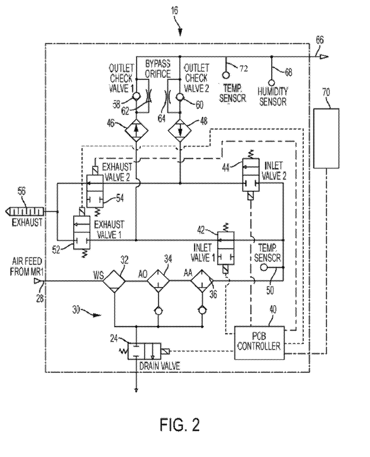
The present invention is a control system for an air dryer that regulates the flow of air through two desiccant towers based on the actual humidity of the air. The system includes a humidity sensor, temperature sensors in the outlet and inlet air, and a desiccant bed to determine when to initiate regeneration. The system optimizes the regeneration cycle for any flow rate and provides a minimum level of performance even if there are sensor or component failures.

Problems solved by technology

Although simple and robust, this control scheme is inefficient and wastes considerable energy.
As a result, the dry product purge air consumed by the air dryer regeneration cycle is wasted.
The second inherent inefficiency of the existing fixed timer regeneration control scheme is that it assumes that the water content of the incoming “wet” air is constant, and the fixed timing cycle is based on the worst case for maximum flow and maximum wet air.

Method used


Image

  • Air dryer control using humidity
  • Air dryer control using humidity
  • Air dryer control using humidity

Examples


example 1

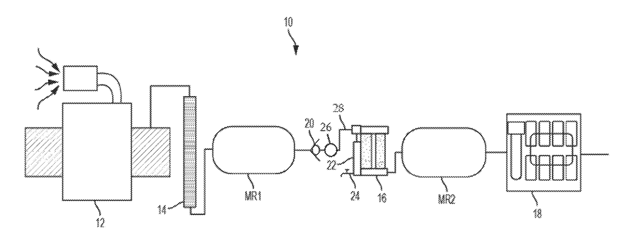
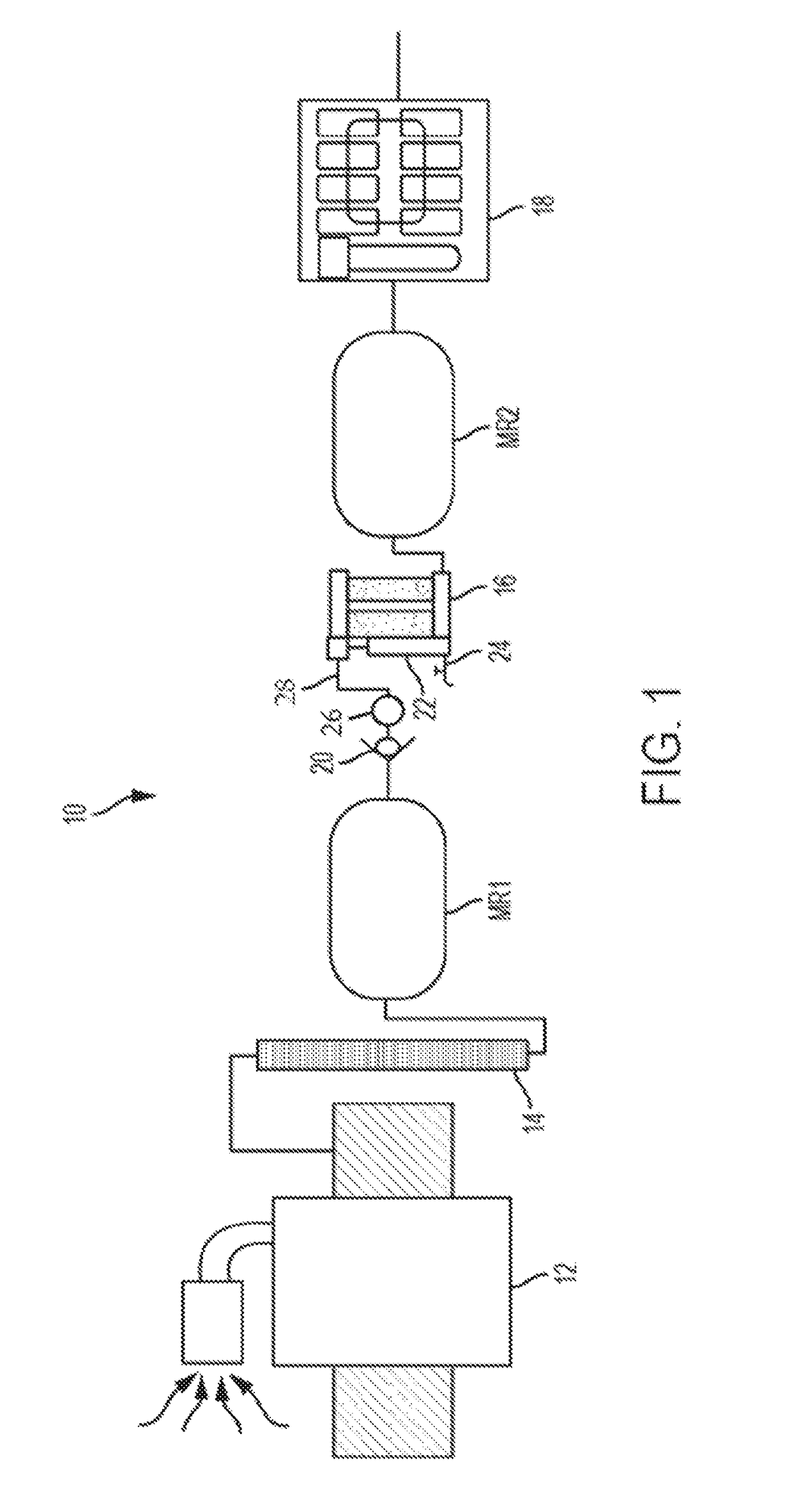
[0028]Referring to FIG. 5, the purge air savings of air dryer verses a conventional control scheme can be estimated using an environmental distribution profile of a target geographic area, such as the United States, representing the amount of time a given locomotive is exposed to environmental temperatures in a typical year. The comparison assumes a locomotive year of 8141 hours (95% of a calendar year), a compressor 12 that runs 1625 loaded hours in a locomotive year, and flow rate through air dryer 16 of 100 SCFM. Train leakage is assumed to be a continuous 20 SCFM. A conventional air dryer is modeled with a 65 second drying cycle and a 65 second regeneration cycle consisting of 48 seconds of purge and 17 seconds of re-pressurization and it is assumed that the conventional air dryer only cycles when the compressor is ON. Purge loss is conservatively assumed to be 15% (15 SCFM), which attempts to account for memory function and flow dependent purge volume.

[0029]Air dryer 16 accordi...

example 2

[0033]In a field trial, air dryer 16 was able to maintain a minimum 40° C. (72° F.) dew point depression, with more than 80% of the purge cycles occurring at the cycle maximum of an hour. In this case, a cycle is the cycle time for tower A and tower B in sequence. For comparison, the same cycle on a conventional air dryer is just under 2 minutes. Because air dryer 16 uses closed-loop humidity feedback to initiate the purge cycle, it accounts for both much lower moisture loading at low temperatures and for actual air flow through the dryer. The optimized purge provides both an energy and air savings by not “wasting” purge air, and importantly reduces the wear and tear on the air dryer components, extending the useful life of air dryer 16. For example, the test air dryer 16 operated for 3427 hours and in that time has made approximately 3000 purge cycles. Had air dryer 16 instead utilized the traditional 2-minute purge (1 minute A, 1 minute B), assuming memory mode operation where it ...


PUM


Abstract

A railway air dryer that switches the flow and counter flow of air through each of two desiccant towers in response to the actual humidity of air being dried by the air dryer. The air dryer includes a humidity sensor, a temperature sensor in the outlet air, and a temperature sensor in the inlet air stream to determine when to initiate the regeneration of the desiccant. The air dryer system is generally specified to provide some minimum drying performance, for example 40° C. dew point suppression.

Description

CROSS-REFERENCE TO RELATED APPLICATIONS[0001]The present application claims priority to U.S. Provisional No. 62 / 236,960, filed Oct. 4, 2016.BACKGROUND OF THE INVENTION[0002]1. Field of the Invention[0003]The present invention relates to desiccant air dryers and, more particularly to a system and method for controlling the regeneration cycle of a twin tower desiccant air dryer.[0004]2. Description of the Related Art[0005]Air dryers for railway use are typically a “pressure-swing adsorption” type, also referred to as a twin-tower, desiccant air dryer. The basic control scheme for switching between the two columns of desiccant is a fixed timer enabled by a “compressor ON” signal from the compressor controls. Whenever the compressor is running, the air dryer cycles between two columns of desiccant at a fixed time cycle to direct wet product air through one column to remove the water vapor, thus resulting in dry product air, while simultaneously taking a fraction of the dry product air a...

Claims


Application Information

Patent Timeline
Patent Type & Authority Applications(United States)
IPC IPC(8): B01D53/04B60T17/00B01D53/26F15B21/048
CPCB01D53/0407B01D53/261B01D2259/4566B01D2257/80B60T17/004B01D53/0454B61H13/34F15B21/048B01D2259/40009
Inventor WRIGHT, ERIC C.
Owner NEW YORK AIR BRAKE CORP
Learn More