
Non-aqueous electrolyte battery

a technology of electrolyte battery and non-aqueous electrolyte, which is applied in the direction of cell components, cell component details, electrochemical generators, etc., can solve the problems of low strength of polyethylene single layer separator, possible melting of microporous film and flow out, and possible piercing and breaking of separators, etc., to achieve excellent reliability and excellent cyclic characteristics and productivity. excellent

Inactive Publication Date: 2017-03-30
MURATA MFG CO LTD
View PDF5 Cites 3 Cited by
  • Summary
  • Abstract
  • Description
  • Claims
  • Application Information

AI Technical Summary

Benefits of technology

The nonaqueous electrolyte battery described in this patent has several technical effects. First, it has good reliability and can control its temperature. Second, it is highly productive and has good cyclic characteristics. Additionally, the battery has a separator with sufficient strength that can absorb heat and lower the internal temperature of the battery if there is an external short-circuit, preventing chemical reactions. The separator also has separate porous films with different average pore sizes to prevent short-circuiting and ensure the proper movement of ions. The microporous film in the cathode side has a larger average pore size to hold more nonaqueous electrolyte and ensure sufficient supply to the cathode. The microporous film in the anode side has a smaller average pore size to prevent the collapse of pores upon charging and discharging cycles. Overall, this battery has excellent performance and stability.

Problems solved by technology

However, as a first problem, although circumstances are different depending on materials, when the temperature of the microporous film made of polyolefin used as the separator for the nonaqueous electrolyte battery reaches shut-down temperature, and further reaches to melt-down temperature as a result of being exposed to an environment in which the temperature of the battery becomes high, there is a fear that the microporous film may be possibly melted and flow out.
Further, since the separator made of a polyethylene single layer is low in its strength, specially, piercing strength, there is a fear that the separator may be possibly pierced and broken so that a short-circuit due to the physical contact of the cathode and the anode is generated.
This may possibly lead to the deterioration of reliability of the battery.
However, since the shut-down of polypropylene is generated at temperature as high as 170° C. or higher near the melting point of lithium, even if the current of the battery is cut off by the shut-down effect, when lithium generates heat as a result of melting due to heat generated in the battery, the heat absorption by the separator cannot come up with the heat generation so that the temperature of the battery may not be possibly assuredly controlled.
That is, under existing circumstances, has not been yet established a nonaqueous electrolyte battery excellent in its reliability in which the temperature of the battery can be assuredly controlled and a possibility of generation of the short-circuit is low.
As a second problem, when the each pore size of the separator is large, active materials falling from the surfaces of the anode and the cathode enter the pores of the separator to easily generate an internal short-circuit.
As a result, the percent defective of the battery is inconveniently increased upon production.
However, when the pore size is simply reduced, the electrolyte solution supplied from the separator becomes undesirably insufficient on the surfaces of the electrodes of the battery, so that lithium ions scarcely come and go between the cathode and the anode upon charging and discharging the battery, and accordingly, cyclic characteristics are deteriorated.

Method used


Image

  • Non-aqueous electrolyte battery
  • Non-aqueous electrolyte battery
  • Non-aqueous electrolyte battery

Examples


example 1

[0074]Now, the present invention will be described on the basis of specific experimental results.

[0075]The porosity and the 90% cumulative pore size of a separator in the following experiments were measured by a mercury porosimeter poremaster 33P (produced by Yuasa Ionic Co., Ltd.) and obtained from a pore distribution curve got from the amount of mercury and pressure relative to the size of pores. The melting point of microporous polyethylene used for the separator was obtained from temperature at which a heat absorption reached a maximum value by carrying out a differential scanning calorimetry (DSC) in accordance with JIS-K-7121 except that temperature rise speed was 5° C. / min.

experiment 1

[Experiment 1]

[0076]In an Experiment 1, the rate of microporous polyethylene relative to the thickness of a separator and the melting point of the microporous polyethylene were examined.

[Sample 1]

[0077]In a Sample 1, a nonaqueous electrolyte battery was manufactured as described below.

[0078]A cathode was manufactured as described below. Initially, lithium cobalt oxide of 85 parts by weight having a composition of LiCoO2, a conductive agent of 10 parts by weight and a binding agent of 5 parts by weight were mixed together to prepare a cathode composite mixture. In this case, as the conductive agent, graphite was used and polyvinylidene fluoride (PVDF) was used as the binding agent.

[0079]Then, the cathode composite mixture was dispersed in N-methylpyrrolidone as a solvent to have slurry. Then, the slurry was uniformly applied to both the surfaces of an elongated aluminum foil having the thickness of 20 μm as a cathode current collector and dried to form a cathode active material layer...

experiment 2

[Experiment 2]

[0108]In an Experiment 2, the thickness of the separator was examined.

[Sample 13]

[0109]In a Sample 13, a cylindrical type nonaqueous electrolyte battery was manufactured in the same manner as that of the Sample 1 except that as the separator, a polyolefin separator made of three layers of microporous polypropylene (PP, thickness of 2 μm)-microporous polyethylene (PE, thickness of 6 μm)-microporous polypropylene (PP, thickness of 2 μm) and having the thickness of 10 μm was used. Here, the microporous polyethylene whose melting point was 131° C. was employed.

[Sample 14]

[0110]In a Sample 14, a cylindrical type nonaqueous electrolyte battery was manufactured in the same manner as that of the Sample 13 except that as the separator, a polyolefin separator made of three layers of microporous polypropylene (PP, thickness of 3.5 μm)-microporous polyethylene (PE, thickness of 8 μm)-microporous polypropylene (PP, thickness of 3.5 μm) and having the thickness of 15 μm was used.

[Sa...


PUM

PropertyMeasurementUnit
porosityaaaaaaaaaa
pore sizeaaaaaaaaaa
particle sizeaaaaaaaaaa

Abstract

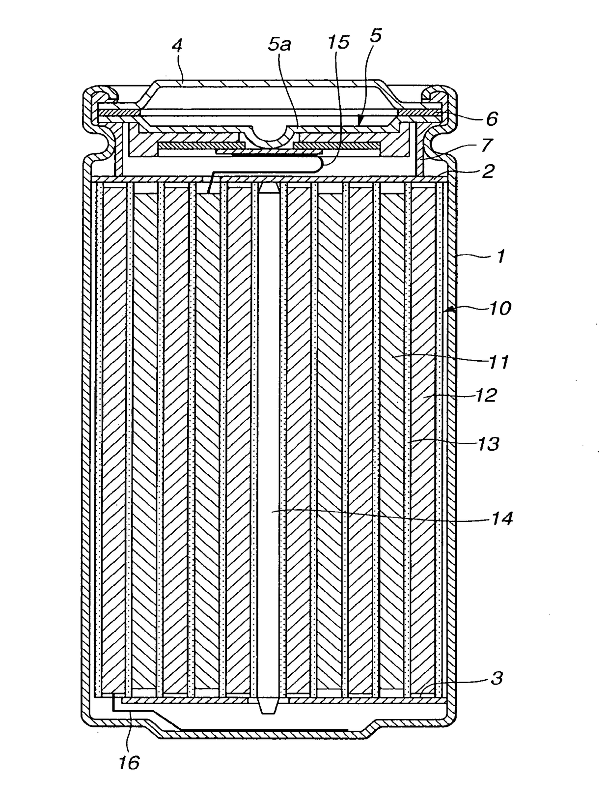
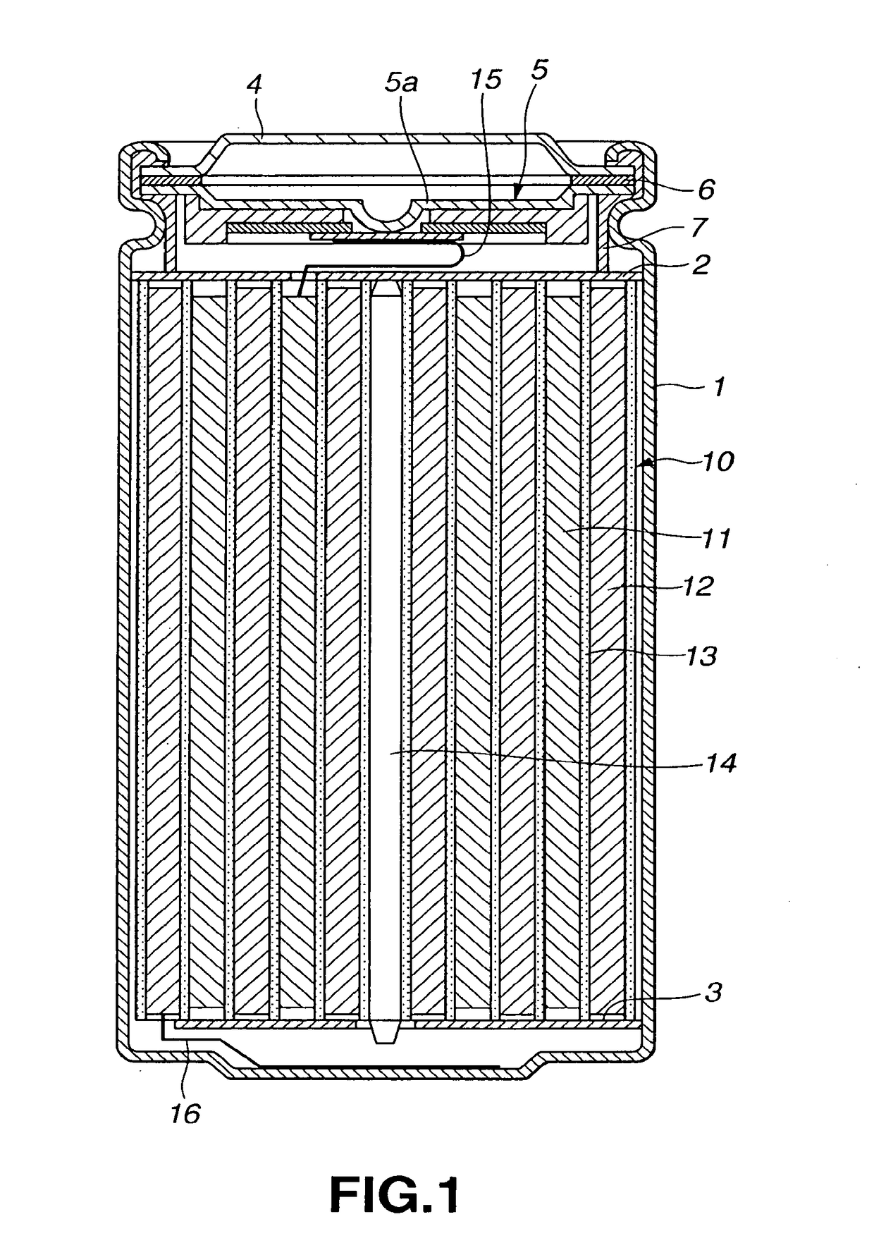
A nonaqueous electrolyte battery with a spirally coiled electrode body (10) including a cathode (11) having a cathode active material and an anode (12) having an anode active material which are coiled through a separator (13) in a battery can (1). As the separator (13), is used a separator having a plurality of laminated microporous films made of polyolefin which have different film layer thickness and average pore size. Specially, the separator (13) has three or more layers of microporous films made of polyolefin laminated. Further, the outermost layer of the separator is made of porous polypropylene and at least one layer of inner layers is made of porous polyethylene. The total of the thickness of layers made of porous polyethylene is located within a range of 40% to 84% as thick as the thickness of the separator. Thus, the temperature of a battery can be controlled, a reliability is enhanced and a productivity and cyclic characteristics are improved.

Description

RELATED APPLICATION DATA[0001]This application is a divisional of U.S. patent application Ser. No. 10 / 467,537 filed Jan. 29, 2004, the entirety of which is incorporated herein by reference to the extent permitted by law. U.S. patent application Ser. No. 10 / 467,537 is the Section 371 National Stage of PCT / JP02 / 01204 filed Feb. 13, 2002. The present application claims the benefit of priority to Japanese Patent Application Nos. JP 2001-037452 filed on Feb. 14, 2001 and JP 2001-076913 filed on Mar. 16, 2001 in the Japan Patent Office, the entireties of which are incorporated by reference herein to the extent permitted by law.TECHNICAL FIELD[0002]The present invention relates to a nonaqueous electrolyte battery including a cathode having a cathode active material, an anode, a nonaqueous electrolyte and a separator. More particularly, the present invention relates to a nonaqueous electrolyte battery in which the separator has a multilayer structure.BACKGROUND ART[0003]In recent years, man...

Claims


Application Information

Patent Timeline
Patent Type & Authority Applications(United States)
IPC IPC(8): H01M2/16H01M10/0525H01M6/10H01M10/05H01M50/417H01M50/449H01M50/489
CPCH01M2/1686H01M10/0525H01M2/1653H01M6/10H01M10/05Y02E60/10H01M50/449H01M50/417H01M50/489
Inventor HOMMURA, HAYATOIMOTO, HIROSHIOMARU, ATSUONAGAMINE, MASAYUKIYAMAGUCHI, AKIRA
Owner MURATA MFG CO LTD
Learn More