Fixing Device

Active Publication Date: 2017-03-30
BROTHER KOGYO KK
View PDF0 Cites 4 Cited by
  • Summary
  • Abstract
  • Description
  • Claims
  • Application Information

AI Technical Summary

Benefits of technology

The patent text describes a fixing device that separates a sheet with an image fixed on it from an endless belt while ensuring the image remains of high quality. The technical effect of this device is to improve the production of fixed images on sheets.

Problems solved by technology

In this case, a longitudinal center portion of the ceramic heater may be deformed in a direction away from the pressure roller, causing uneven pressure distribution, in the longitudinal direction, at the nip potion, which may be result in variation in quality of an image fixed on a sheet.

Method used


Image

  • Fixing Device
  • Fixing Device
  • Fixing Device

Examples


Embodiment Construction

[0024]An illustrative embodiment according to one or more aspects of the disclosure will be described below with reference to the accompanying figures. The disclosure is merely an example and various changes, arrangements and modifications may be applied without departing from the spirit and scope of the disclosure. The overall structure of a color printer 1 will be described first, and then various parts thereof will be described in detail.

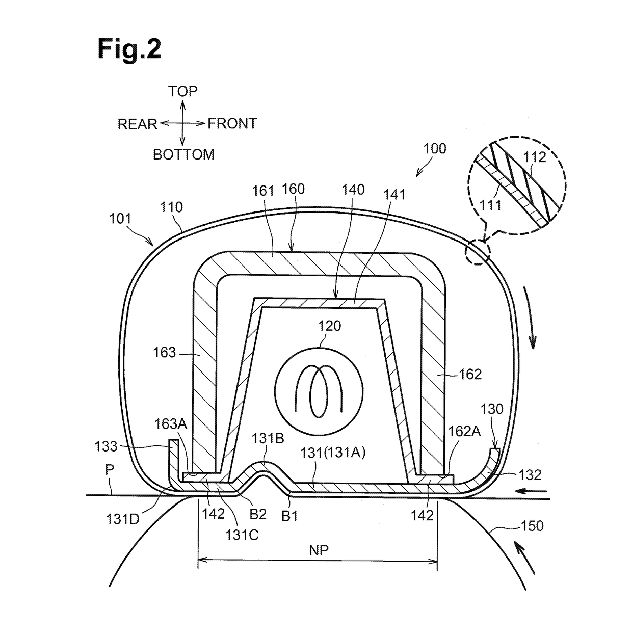
[0025]For ease of discussion, in the following description, the top or upper side, the bottom or lower side, the left or left side, the right or right side, the front or front side, and the rear or rear side of the color printer 1 will be identified as indicated by the arrows in FIG. 1.

[0026]As shown in FIG. 1, the color printer 1 includes, in a housing 10, a sheet feeder 20 configured to feed a recording sheet, e.g., a sheet P, an image forming unit 30 configured to form an image on the sheet P fed by the sheet feeder 5, and a discharge unit 90 ...


PUM


Abstract

A nip member is disposed inside the endless belt and elongated in a longitudinal direction. A backup member sandwiches the endless belt against the nip member to form a nip portion at which the backup member and the endless belt are in contact with each other and configured to convey a recording sheet in a conveying direction perpendicular to the longitudinal direction. A downstream end of the nip portion in the conveying direction is arced with a longitudinal center portion thereof further upstream than longitudinal end portions thereof. The nip member includes a first portion sandwiching the endless belt against the backup member, and a second portion positioned downstream of the first portion in the conveying direction and bent in a direction away from the backup member. The second portion is arced with a longitudinal center portion thereof further upstream in the conveying direction than longitudinal end portions thereof.

Description

CROSS-REFERENCE TO RELATED APPLICATION[0001]This application claims priority from Japanese Patent Application No. 2015-193911 filed on Sep. 30, 2015, the content of which is incorporated herein by reference in its entirety.FIELD OF DISCLOSURE[0002]Aspects of the disclosure relate to a fixing device configured to thermally fix a developer image onto a recording sheet.BACKGROUND[0003]A known fixing device includes an endless belt rotating about its axis, a ceramic heater disposed inside the endless belt and having a rectangular shape elongated in an axial direction of the endless belt, and a pressure roller sandwiching the endless belt against the ceramic heater to form a nip portion. A sheet is conveyed in a conveying direction while being sandwiched by the endless belt and the pressure roller, and is separated from the endless belt at a downstream end of the ceramic heater.SUMMARY[0004]In the above-described configuration, it is conceivable that longitudinal opposite ends of the cer...

Claims


Application Information

Patent Timeline
IPC IPC(8): G03G15/20
CPCG03G15/2053G03G2215/0141G03G2215/2035G03G15/2017
Inventor KAJITA, MASAHITO
Owner BROTHER KOGYO KK
Why Eureka
Try Eureka