Sealed container, thermal insulator, and gas adsorption device

Active Publication Date: 2017-03-23
PANASONIC INTELLECTUAL PROPERTY MANAGEMENT CO LTD
View PDF2 Cites 2 Cited by
  • Summary
  • Abstract
  • Description
  • Claims
  • Application Information

AI Technical Summary

Benefits of technology

The present invention provides a gas adsorption device made of copper ion-exchanged ZSM-5 type zeolite with good gas adsorption capabilities. The device is sealed to prevent contact with air and minimize consumption. It can be used in a sealed container with a barrier or a thermal insulator. This invention solves the problem of increased consumption caused by air contact and provides a simplified solution for gas adsorption.

Problems solved by technology

Generally, in a sealed container or a thermal insulator that delivers performance by a high degree of vacuum environment or an inert gas atmosphere having a high purity, such as in a vacuum thermally insulating container, a vacuum thermal insulator, or a plasma display panel, an internal pressure rise brought about by a gas remaining at a time of production or a gas penetrating with lapse of time constitutes a cause of deterioration of the performance of the sealed container or the thermal insulator.
However, there is a problem that, when these gas adsorption devices are brought into contact with air before being applied to the thermal insulator, the gas-adsorptive substance adsorbs the air component and the like, and thus a part of the gas-adsorptive substance is consumed.
The device disclosed in PTL 1 has a problem that the Ba-Li alloy has a comparatively low capability to adsorb nitrogen, and the adsorption speed is slow.
However, there is a problem that, because reach of the air cannot be prevented, part of the Ba-Li alloy is consumed.
Meanwhile, there is a problem that this control needs the external force, that a cost for imparting a mechanism to the container is needed, and the like.
In addition, there is a problem that, when the residual gas that is present in the inside of the outer covering material and that has not been removed by the industrial vacuum gas-discharging step contains moisture, consumption of the gas adsorption material by moisture adsorption cannot be suppressed.
For this reason, there is a problem of increase in a number of manufacturing steps.
For this reason, this gas adsorption device has a problem of decrease in the capability to adsorb the residual air that is present in the inside of the outer covering material and that has not been removed by the industrial vacuum gas-discharging step.

Method used


Image

  • Sealed container, thermal insulator, and gas adsorption device
  • Sealed container, thermal insulator, and gas adsorption device
  • Sealed container, thermal insulator, and gas adsorption device

Examples


first exemplary embodiment

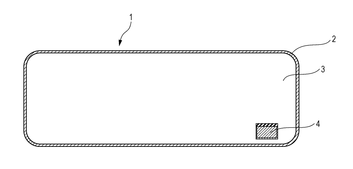
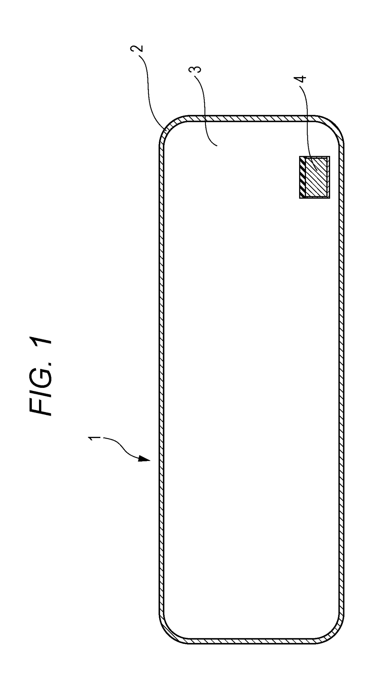
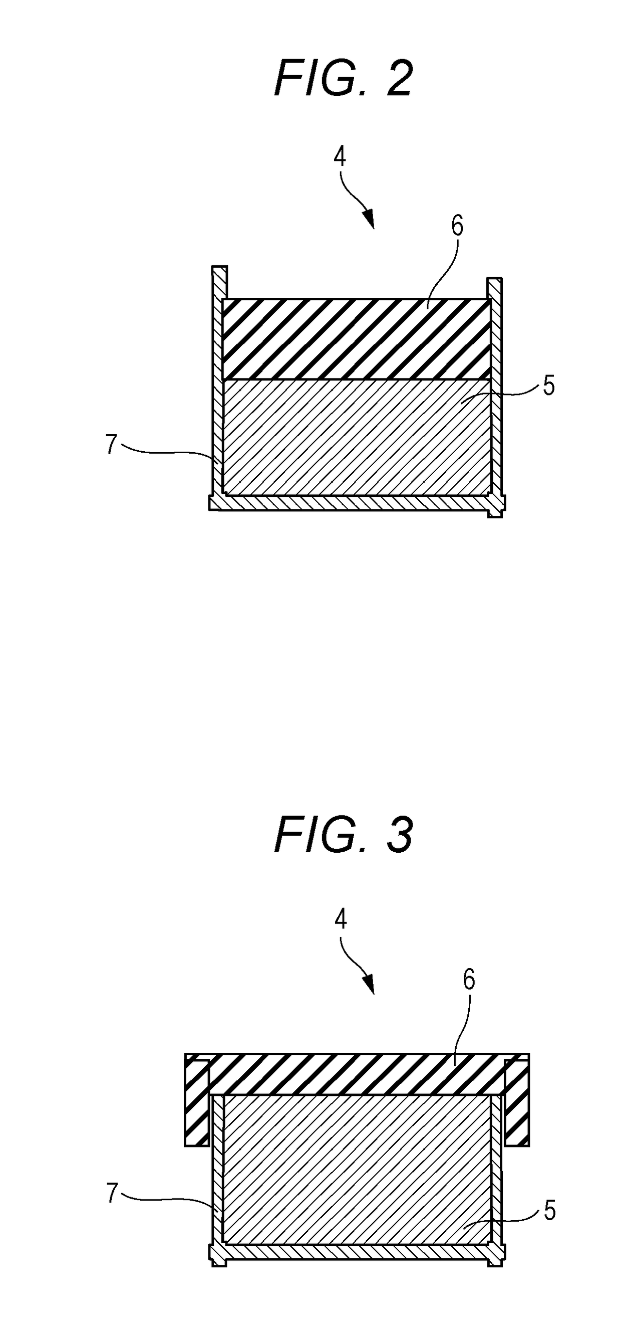
[0038]FIG. 1 is a sectional view of a sealed container in a first exemplary embodiment of the present invention. FIG. 2 and FIG. 3 are sectional views of examples of a gas adsorption device in the first exemplary embodiment of the present invention.

[0039]Referring to FIG. 1, sealed container 1 of the present exemplary embodiment is made of at least outer container 2 constituting sealed container 1, sealed space 3 formed by outer container 2, and gas adsorption device 4 being provided in sealed space 3 and being capable of adsorbing a gas. Further, as shown in detail in FIG. 2, gas adsorption device 4 includes at least copper ion-exchanged ZSM-5 type zeolite 5 and primary material 6 having a lower gas barrier property than outer container 2 does.

[0040]Adsorption device 4 in FIG. 2 has a structure in which container 7 is filled with copper ion-exchanged ZSM-5 type zeolite 5 and primary material 6 having a lower gas barrier property than outer container 2 does. Referring to FIG. 3, ads...

second exemplary embodiment

[0073]FIG. 4 is a sectional view of a thermal insulator in a second exemplary embodiment of the present invention. FIG. 5 is a sectional view of one example of a gas adsorption device in the second exemplary embodiment of the present invention. FIG. 6 is a sectional view of another example of the gas adsorption device in the second exemplary embodiment of the present invention. FIG. 7 is a sectional view of still another example of the gas adsorption device in the second exemplary embodiment of the present invention.

[0074]Referring to FIG. 4, thermal insulator 8 of the present exemplary embodiment includes at least core material 9 and gas adsorption device 4 capable of adsorbing a gas, as well as outer covering material 10 having a gas barrier property and covering core material 9 and gas adsorption device 4, a pressure of an inside of outer covering material 10 being reduced. Gas adsorption device 4 includes at least copper ion-exchanged ZSM-5 type zeolite 5 described in the first ...

example 1

[0108]In Example 1, the gas adsorption device has a structure shown in FIG. 2. After a container made of aluminum is filled with 1.5 g of copper ion-exchanged ZSM-5 type zeolite 5 and an alumina-based ceramic porous body serving as primary material 6 having a lower gas barrier property than the outer covering material does, a thermal treatment is carried out at 600° C. under a reduced pressure, so as to fabricate the gas adsorption device. The structure is such that the alumina-based ceramic porous body covers copper ion-exchanged ZSM-5 type zeolite 5.

[0109]As a result of evaluation on the thermal insulator fabricated by using this gas adsorption device, the outer appearance is such that a site where the gas adsorption device is disposed is convex as compared to the thickness of a site where the gas adsorption device is not disposed. This is due to a following reason. Because the alumina-based ceramic porous body is disposed to cover copper ion-exchanged ZSM-5 type zeolite 5, the ga...


PUM

PropertyMeasurementUnit
Pressureaaaaaaaaaa
Adsorption entropyaaaaaaaaaa
Thermal insulatoraaaaaaaaaa

Abstract

A sealed container (1) includes at least an outer container (2) and a gas adsorption device (4) being provided in a sealed space (3) within the outer container (2) and being capable of adsorbing a gas. The gas adsorption device (4) includes at least a copper ion-exchanged ZSM-5 type zeolite and a primary material having a lower gas barrier property than the outer container (2) does.

Description

TECHNICAL FIELD[0001]The present invention relates to a sealed container, a thermal insulator, and a gas adsorption device that is applied to the sealed container and the thermal insulator.BACKGROUND ART[0002]Generally, in a sealed container or a thermal insulator that delivers performance by a high degree of vacuum environment or an inert gas atmosphere having a high purity, such as in a vacuum thermally insulating container, a vacuum thermal insulator, or a plasma display panel, an internal pressure rise brought about by a gas remaining at a time of production or a gas penetrating with lapse of time constitutes a cause of deterioration of the performance of the sealed container or the thermal insulator. Thus, in order to adsorb these gases, a sealed gas adsorption device filled with a gas adsorption material is proposed.[0003]For example, numerous gas adsorption devices are proposed that are applied to a vacuum thermal insulator formed by covering a core material with an outer cov...

Claims


Application Information

Patent Timeline
IPC IPC(8): F16L59/065B01D53/26B01J20/18B01D53/04
CPCF16L59/065B01D53/04B01D53/261B01D2257/80B01D2253/108B01D2253/25B01J20/18B01D53/0407B01D2253/102B01D2253/106B01D2257/102B01D2259/4525
Inventor YUASA, AKIKO
Owner PANASONIC INTELLECTUAL PROPERTY MANAGEMENT CO LTD
Why Eureka
Try Eureka