Gas filling method

a technology of gas filling and gas chamber, which is applied in the direction of container filling under pressure, electrochemical generator, container discharging method, etc., can solve the problems of inaccurateness, rapid increase in pressure and temperature of connected tanks, etc., and achieve the effect of reliable determination of initial pressure and prolonged acquisition time of initial pressur

Active Publication Date: 2017-03-16
HONDA MOTOR CO LTD
View PDF3 Cites 7 Cited by
  • Summary
  • Abstract
  • Description
  • Claims
  • Application Information

AI Technical Summary

Benefits of technology

[0031](9) When determining the initial pressure in a tank by the gas filling method according to the present invention, the check valve at the tank needs to be closed when initial filling is started. According to the present invention, a pressure at the detection point in the upstream piping may be maintained lower than a predetermined minimum residual pressure expected for the tank after the completion of main filling but before the start of a next initial filling. This can ensure that the pressure in the piping is lower than the pressure in the tank such that the check valve at the tank is in the closed position when initial filling is started. Therefore, the present invention can reliably determine the initial pressure even when the residual pressure in the tank is low.
[0032](10) When the press

Problems solved by technology

Therefore, the pre-shot method may induce rapid increase in the pressure and temperature of a connected t

Method used


Image

  • Gas filling method
  • Gas filling method
  • Gas filling method

Examples


first embodiment

[0040]Below, a first embodiment of the present invention will be described with reference to the figures. FIG. 1 shows the configuration of a hydrogen filling system S in which the hydrogen gas filling method according to this embodiment is used. The hydrogen filling system S includes the combination of a fuel cell vehicle V which runs on hydrogen gas as a fuel gas and a hydrogen station 9 as a supply system which supplies hydrogen gas to a hydrogen tank of the vehicles V. Below, the configuration of the hydrogen station 9 will first be described, and the configuration of the vehicle V will then be described.

[0041]The hydrogen station 9 includes a pressure accumulator 91 in which a high-pressure hydrogen gas to be supplied to the vehicle V is stored, a station piping 93 extending from the pressure accumulator 91 to a filling nozzle 92 for discharging hydrogen gas, a cutoff valve 94a and a flow control valve 94b provided in the station piping 93, a venting device 99 for handling hydr...

second embodiment

[0080]Below, a second embodiment of the present invention will be described with reference to the figures. Note that illustrations and descriptions for those shared with the first embodiment are omitted when this embodiment is described below.

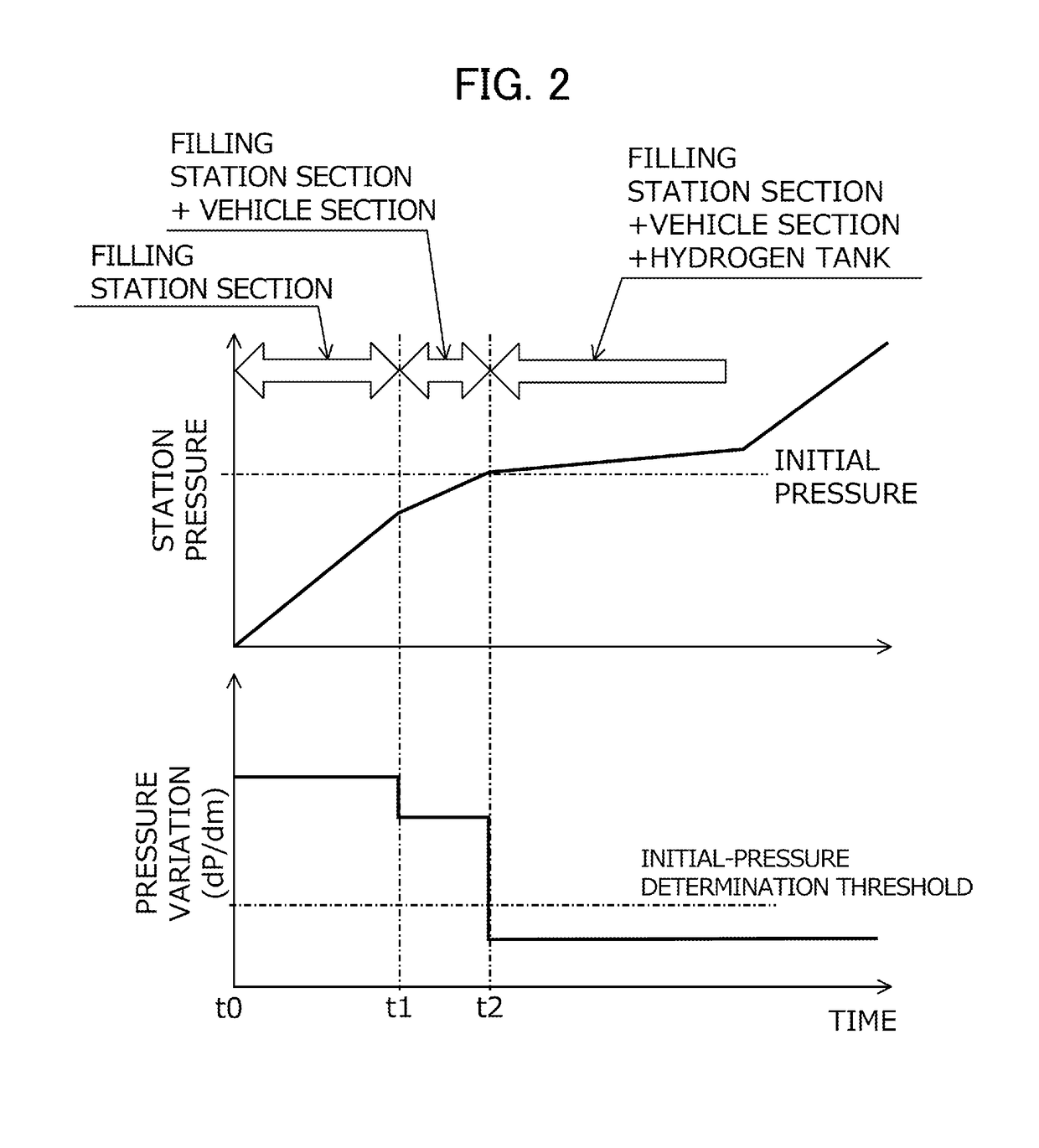
[0081]In the hydrogen gas filling method according to the first embodiment, an initial-pressure determination threshold is set for the pressure variation, and the initial pressure is obtained at a time when the value of the pressure variation obtained during initial filling becomes this initial-pressure determination threshold or less as described with reference to FIG. 3. Meanwhile, pressure loss may occur in the piping when connecting the hydrogen tank to the pressure accumulator through the piping, and supplying hydrogen gas to the hydrogen tank from the pressure accumulator. Further, this pressure loss becomes larger as the pressure in the hydrogen tank decreases and the volume flow rate of hydrogen gas increases. The pressure difference be...

third embodiment

[0087]Next, a third embodiment of the present invention will be described with reference to the figures. Note that illustrations and descriptions for those shared with the first embodiment are omitted when this embodiment is described below.

[0088]In the hydrogen gas filling method according to the first embodiment, an initial-pressure determination threshold is set for the pressure variation, and the initial pressure is obtained at a time when the value of the pressure variation obtained during initial filling becomes this initial-pressure determination threshold or less as described with reference to FIG. 3. The hydrogen gas filling method according to this embodiment differs from that according to the first embodiment by a way of determining a timing of obtaining the initial pressure. The hydrogen gas filling method according to this embodiment differs from the hydrogen gas filling method according to the first embodiment in that a timing of obtaining the initial pressure is deter...


PUM


Abstract

Provided is a gas filling method capable of accurately determining the initial pressure in a tank while minimizing increase in temperature and pressure regardless of the capacity of the tank. The gas filling method for connecting a supply source to a tank via a piping, and filling the tank with the gas, the method includes: an initial-filling initiation step of opening a flow control valve provided in the piping to start initial filling; a pressure-variation acquisition step of obtaining a pressure variation per unit time at a predetermined detection point downstream of the flow control valve in the piping; an initial-pressure detection step of obtaining a pressure at the detection point at a time specified using the pressure variation, and considering that pressure as the initial pressure in the tank; and a main-filling initiation step of starting main filling using the initial pressure.

Description

[0001]This application is based on and claims the benefit of priority from Japanese Patent Application No. 2015-178742, filed on 10 Sep. 2015, the content of which is incorporated herein by reference.BACKGROUND OF THE INVENTION[0002]Field of the Invention[0003]The present invention relates to a gas filling method. More specifically, the present invention relates to a gas filling method including connecting a supply source of a compressed gas to a tank mounted on a mobile object, and filling the tank with the gas.[0004]Related Art[0005]A fuel cell vehicle runs on a motor powered by a fuel cell where air containing oxygen and hydrogen gas as a fuel gas supplied thereto generate electricity. Fuel cell vehicles, in which those fuel cells are used as energy sources for generating power, recently have been becoming closer to practical use. Hydrogen gas is required to generate electricity in a fuel cell. A recent mainstream fuel cell vehicle uses tank-filled hydrogen gas for running, in wh...

Claims


Application Information

Patent Timeline
IPC IPC(8): F17C5/06F17C13/04F17C13/08F17C1/00
CPCF17C5/06F17C2270/0763F17C13/04F17C13/084F17C2201/056F17C2205/0335F17C2205/0326F17C2221/012F17C2223/0123F17C2223/035F17C2225/0123F17C2225/035F17C2250/032F17C2250/0434F17C2250/0626F17C2260/025F17C1/005F17C5/007F17C2205/0332F17C2223/036F17C2225/036F17C2227/0337F17C2227/0388F17C2250/034F17C2250/043F17C2250/0439F17C2250/0443F17C2250/0636F17C2265/065F17C2270/0139Y02E60/32
Inventor HANDA, KIYOSHI
Owner HONDA MOTOR CO LTD
Why Eureka
Try Eureka