
Swirl nozzle assemblies with high efficiency mechanical break up for generating mist sprays of uniform small droplets

a technology of mechanical breakage and swirl nozzle, which is applied in the direction of spray nozzle, liquid dispensing, single-unit apparatus, etc., can solve the problems of undesirable phenomena and poor misting performance, and achieve the effect of cost-effectiveness

Active Publication Date: 2017-03-09
DLHBOWLES INC
View PDF7 Cites 8 Cited by
  • Summary
  • Abstract
  • Description
  • Claims
  • Application Information

AI Technical Summary

Benefits of technology

The present invention is a new nozzle assembly that solves the problems of poor misting performance in previous swirl cup nozzles. The new nozzle assembly has two unique features that reduce internal shear losses and improve spray atomization. The first feature is a swirled spray with significantly increased rotating or angular velocity, resulting in smaller droplets. The second feature is a distally projecting swirling spray with reduced coagulation, further reducing and maintaining smaller droplets. The new nozzle assembly is cost-effective and can reliably generate a swirling spray of droplets of a selected small size, with reduced droplet recombination and undesirable spray effects like splattering.

Problems solved by technology

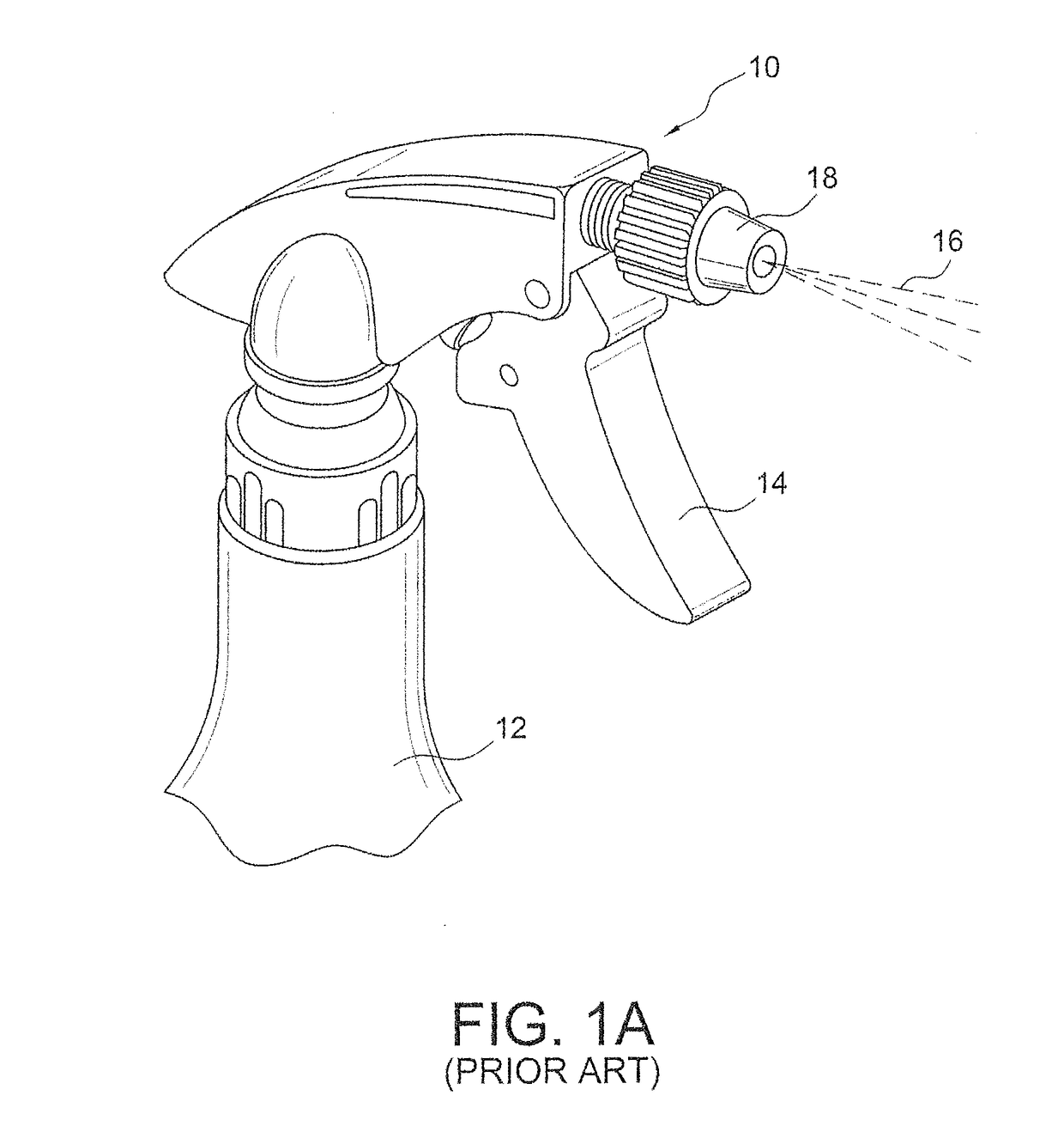
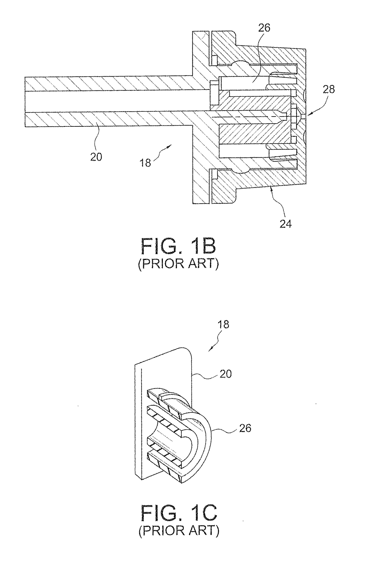
This traditional swirl cup configuration causes the droplets generated in the swirl chamber to accelerate distally along the tubular lumen of the exit and to coagulate or recombine into droplets of irregular large sizes having excessive distally projected linear velocity, causing a poor misting performance.
This phenomena is undesirable when the application calls for a fine mist (e.g., as used in many hair care products).

Method used


Image

  • Swirl nozzle assemblies with high efficiency mechanical break up for generating mist sprays of uniform small droplets
  • Swirl nozzle assemblies with high efficiency mechanical break up for generating mist sprays of uniform small droplets
  • Swirl nozzle assemblies with high efficiency mechanical break up for generating mist sprays of uniform small droplets

Examples


first embodiment

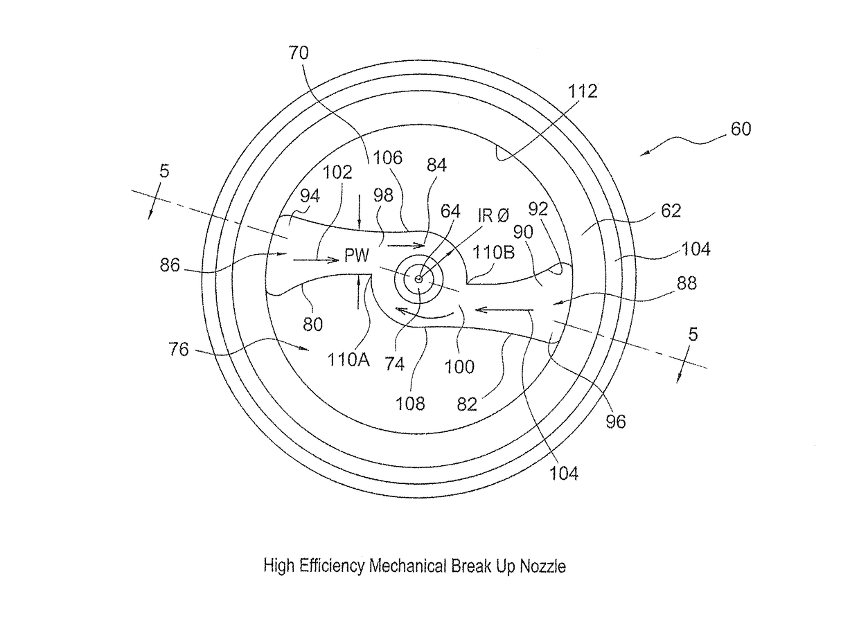
[0045]The fluidic nozzle assembly of the present invention incorporates the spray head and sealing post structure of the standard nozzle assembly, but discards the flawed performance of the standard swirl cup (e.g., 30). Thus, the present invention is directed to a new High-Efficiency Mechanical Break-Up (“HE-MBU”) nozzle assembly, illustrated in FIGS. 4-9, which avoids these problems while maximizing the creation and preservation of small droplets which are distally sprayed or issued at a very high angular velocity. the present invention provides two principal improvements over spray generation performance of traditional swirl nozzles of the prior art, namely: (1) a swirled spray with Increased rotating or angular velocity ω, resulting in smaller droplet size, and (2) a swirled spray with reduced coagulation, further reducing & maintaining smaller droplet size in the fluid product spray.

[0046]In the first form of the invention illustrated in FIG. 4, a cup-shaped High-Efficiency Mec...

third embodiment

[0073]FIGS. 11 and 12 illustrate the present invention wherein an opposing rotation HE-MBU nozzle member 220 is also configured as a cup-shaped solid, as illustrated in the above-described embodiments, wherein similar features are similarly numbered. In this embodiment, a cylindrical sidewall 62 surrounds a distally projecting central axis 64 and terminates in a distal end wall 68 having a circular interior surface 70 and an exterior or distal surface 72. In the illustrated embodiment, distal end wall 68 has first and second outlet channel or exit orifices 230 and 232, each providing fluid communication between the interior and exterior of the cup.

[0074]Formed in the interior surface 70 of nozzle 220 are first and second HE-MBU enhanced swirl inducing mist generating structure 222 and 224 incorporating respective interaction regions 226 and 228 surrounding their respective orifices 230 and 232. The first or left enhanced swirl inducing mist generating structure 222 incorporates a pa...


PUM


Abstract

A spray dispenser is configured to generate a swirled output spray pattern 152 with improved rotating or angular velocity ω and smaller sprayed droplet size. Cup-shaped nozzle member 60 has a cylindrical side wall 62 surrounding a central longitudinal axis 64 and has a circular closed end wall 68 with at least one exit aperture 74 passing through the end wall. At least one enhanced swirl inducing mist generating structure is formed in an inner surface 70 of the end wall, and including a pair of opposed inwardly tapered offset power nozzle channels 80, 82 terminating in an interaction chamber 84 surrounding the exit aperture 74. The power nozzle channels generate opposing offset flows which are aimed to very efficiently generate a vortex of fluid which projects distally from the exit aperture as a swirled spray of small droplets 152 having a rapid angular velocity.

Description

REFERENCE TO RELATED APPLICATIONS[0001]This application claims the priority benefit of prior commonly owned copending U.S. provisional patent application No. 62 / 022,290, filed on Jul. 9, 2014, and entitled “Swirl Nozzle Assemblies with High Efficiency Mechanical Break up for Generating Mist Sprays of Uniform Small Droplets” (Improved Offset Mist Swirl Cup and Multi-Nozzle Cup), and further claims the priority benefit of prior copending U.S. provisional patent application No. 61 / 969,442, filed Mar. 24, 2014 and entitled “Swirl Nozzle Assembly with High Efficiency Mechanical Break up for Generating Mist Sprays of Uniform Small Droplets” (Mist Swirl Cup). This application is also related to commonly owned U.S. Pat. No. 7,354,008 entitled “Fluidic Nozzle for Trigger Spray Applications” and PCT application number PCT / US12 / 34293, entitled “Cup-shaped Fluidic Circuit, Nozzle Assembly and Method” issued on Apr. 8, 2008 to Hester et al (now WIPO Pub WO 2012 / 145537). The entire disclosures of...

Claims


Application Information

Patent Timeline
IPC IPC(8): B05B1/34B05B11/00
CPCB05B11/30B05B1/3436B65D83/14B05B11/10B65D83/20
Inventor GOPALAN, SHRIDHARHARTRANFT, EVAN
Owner DLHBOWLES INC
Learn More