
X-ray analysis device

Active Publication Date: 2017-03-02
HITACHI HIGH TECH SCI CORP
View PDF4 Cites 3 Cited by
  • Summary
  • Abstract
  • Description
  • Claims
  • Application Information

AI Technical Summary

Benefits of technology

The invention provides an X-ray analysis device that can detect X-rays with high energy resolution and counting efficiency without occupying multiple mounting ports. By adjusting the distance between the optical member and the first and second detection units, the device can prioritize energy resolution or counting efficiency, and easily switch between regions. Additionally, the device can maintain a low dead time for detecting characteristic X-rays and reduce the overlap frequency of detection signals.

Problems solved by technology

However, as in the related art described above, in a case where two kinds of detectors are integrated, when performing a measurement with high energy resolution, X-rays which are incident on a detector with high counting efficiency become wasteful, and the counting efficiency of a detector with low counting efficiency is further deteriorated.
In addition, in a case where, of superconducting detectors, an STJ with comparatively high counting efficiency and a TES with comparatively excellent energy resolution are attached in combination, in addition to the two mounting ports being occupied, there is a problem in that a plurality of refrigerators are required and costs and an installation space required for a device configuration are high.
As in the related art described above, in a case where X-rays are condensed using an optical element, since the maximum count rate of the detection element does not change, there is a concern that it may not be possible to improve the counting efficiency.

Method used


Image

  • X-ray analysis device
  • X-ray analysis device
  • X-ray analysis device

Examples


Embodiment Construction

[0047]Hereinafter, an X-ray analysis device according to an embodiment of the invention will be described referring to the accompanying drawings.

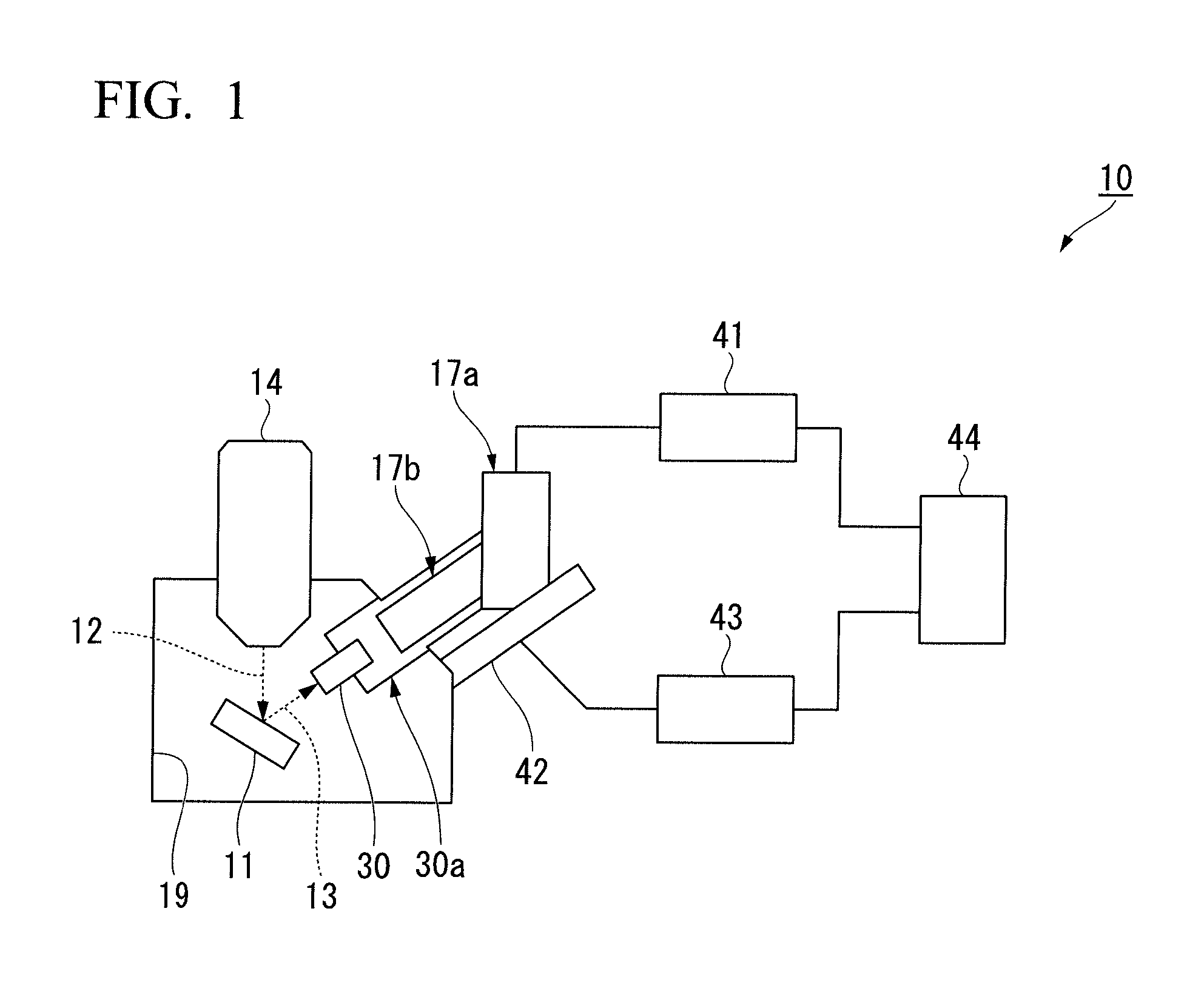
[0048]An X-ray analysis device 10 of this embodiment is usable as, for example, a composition analysis device, such as an electron microscope, an ion microscope, an X-ray microscope, or a fluorescent X-ray analysis device.

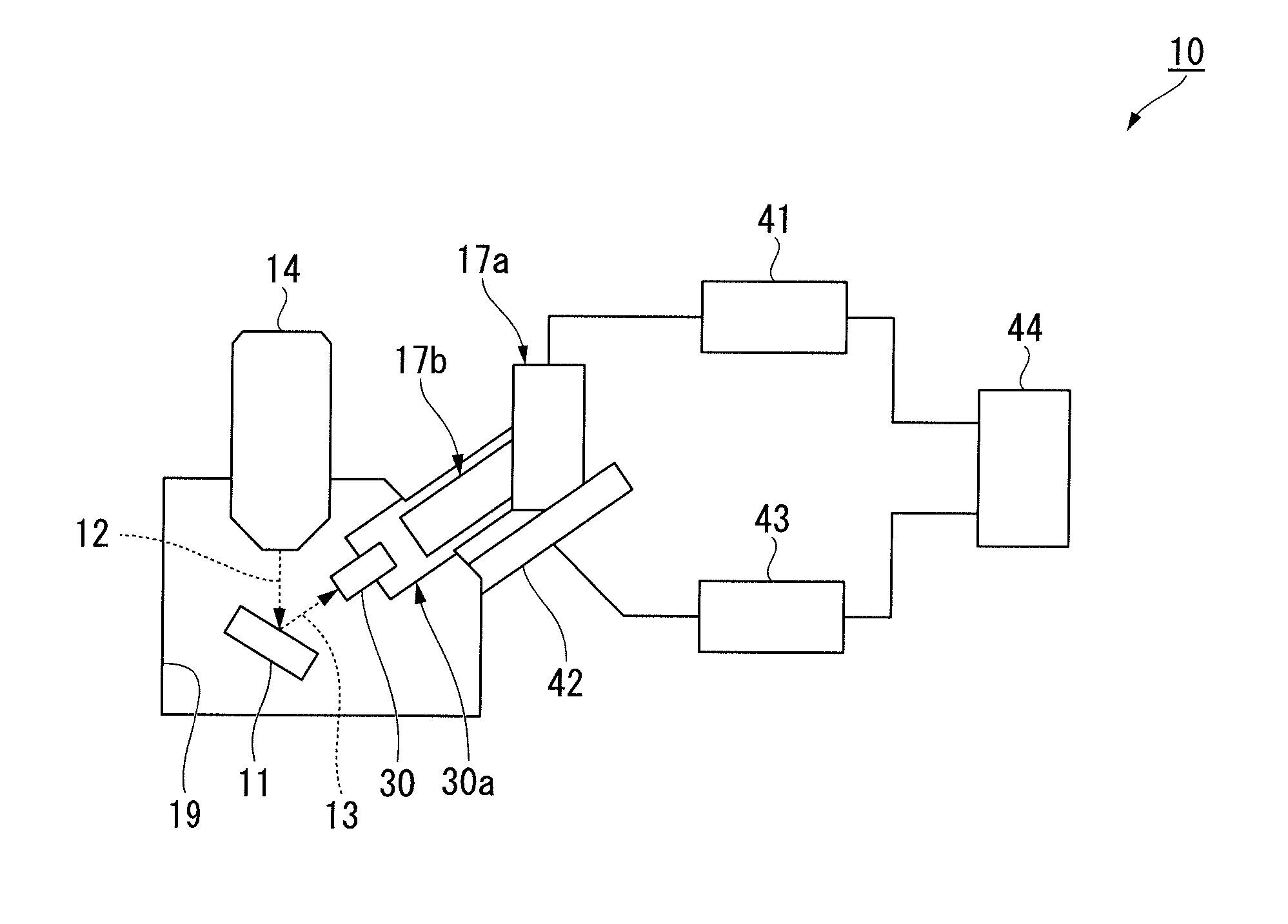
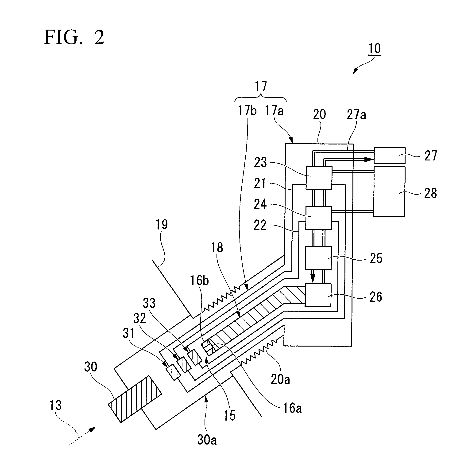
[0049]As shown in FIGS. 1 and 2, the X-ray analysis device 10 includes an electron gun 14 which irradiates a sample 11 to be analyzed with an electron beam 12 to excite the sample 11, and an X-ray detector 15 which detects characteristic X-rays 13 emitted from the excited sample 11.

[0050]The X-ray detector 15 includes a first detection unit 16a and a second detection unit 16b which have, for example, a superconducting transition edge sensor (Transition Edge Sensor, TES) as an X-ray detection unit.

[0051]The TES uses superconducting transition of a superconductor, and maintains an operation point in an intermediate state bet...


PUM


Abstract

An X-ray analysis device includes an electron gun, an X-ray optical member, a first detection unit and a second detection unit, and a distance changing mechanism. The X-ray optical member guides characteristic X-rays emitted from a sample to at least any one of the first detection unit or the second detection unit. The first detection unit is formed such that energy resolution is given relative priority over counting efficiency in contrast to the second detection unit. The second detection unit is formed such that counting efficiency is given relative priority over energy resolution in contrast to the first detection unit. The distance changing mechanism changes the distance between each of the first detection unit and the second detection unit and the X-ray optical member in an axial direction of an optical axis of the X-ray optical member.

Description

BACKGROUND OF THE INVENTION[0001]Field of the Invention[0002]The present invention relates to an X-ray analysis device including an energy dispersive radiation detector, such as a superconducting transition edge sensor. The present application claims priority based on Japanese Patent Application No. 2015-166549 filed in Japan on Aug. 26, 2015, the disclosures of which are incorporated herein by reference in their entirety.[0003]Description of Related Art[0004]As an X-ray analysis device which can perform energy discrimination of X-rays, an energy dispersive X-ray detector (Energy Dispersive Spectroscopy, hereinafter, referred to as EDS) or a wavelength dispersive X-ray detector (Wavelength Dispersive Spectroscopy, hereinafter, referred to as WDS) is known.[0005]An EDS is a type of X-ray detector which converts the energy of X-rays taken into the detector to an electrical signal in the detector and calculates energy according to the magnitude of the electrical signal. A WDS is a type...

Claims


Application Information

Patent Timeline
IPC IPC(8): G21K7/00G01N23/223
CPCG01N23/223G21K7/00
Inventor NAKAYAMA, SATOSHITANAKA, KEIICHINAGATA, ATSUSHICHINONE, KAZUO
Owner HITACHI HIGH TECH SCI CORP
Learn More