
Toolholder with viscous fluid inertial mass damper

Active Publication Date: 2017-03-02
KENNAMETAL INC
View PDF1 Cites 4 Cited by
  • Summary
  • Abstract
  • Description
  • Claims
  • Application Information

AI Technical Summary

Benefits of technology

The patent text describes a solution for reducing vibrations in a toolholder by using a viscous fluid inertia mass damper. This damper is placed in the central cavity of the toolholder and has a reservoir for containing the viscous fluid and multiple openings for the fluid to flow through. This results in damping, which helps to suppress the vibrations of the toolholder. The technical effect of this invention is to improve the stability and accuracy of the toolholder, which can lead to better performance and efficiency in manufacturing processes.

Problems solved by technology

During a metal cutting operation, any vibratory motion between a toolholder and workpiece may lead to undesirable cutting performances such as poor workpiece surface finish and out-of-tolerance finished workpieces.
Furthermore, such vibration may cause the toolholder or the machine tool to become damaged.
However, this approach interferes with production and only minimally reduces the amount of vibration.
However, solid carbide is extremely expensive.
Furthermore, although chatter and vibration are reduced by the inherently high density of the solid carbide bar, vibration nonetheless may build to an unacceptable level.
Still furthermore, solid carbide is fairly brittle and a minor impact upon the boring bar during use or setup may inadvertently damage the bar.
However, even with such a design available, each time the boring bar is to be used under different conditions, it must be tuned using sophisticated equipment that may or may not be available on the shop floor.

Method used


Image

  • Toolholder with viscous fluid inertial mass damper
  • Toolholder with viscous fluid inertial mass damper
  • Toolholder with viscous fluid inertial mass damper

Examples


Embodiment Construction

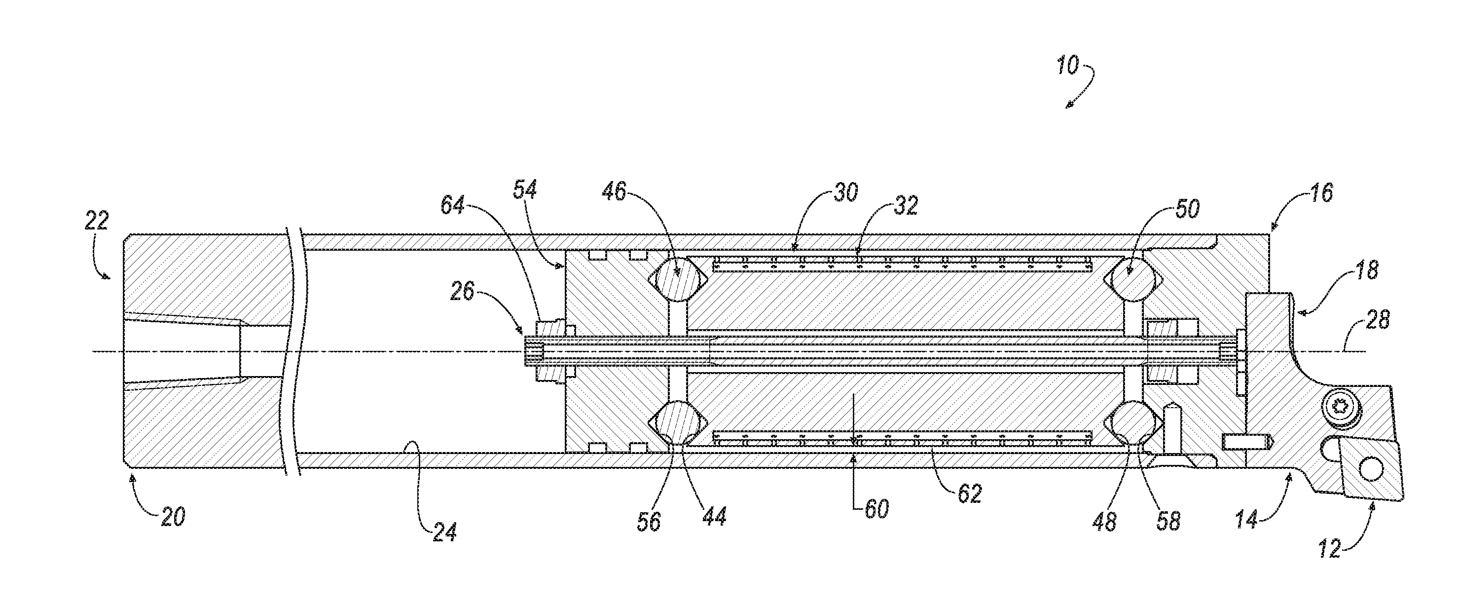
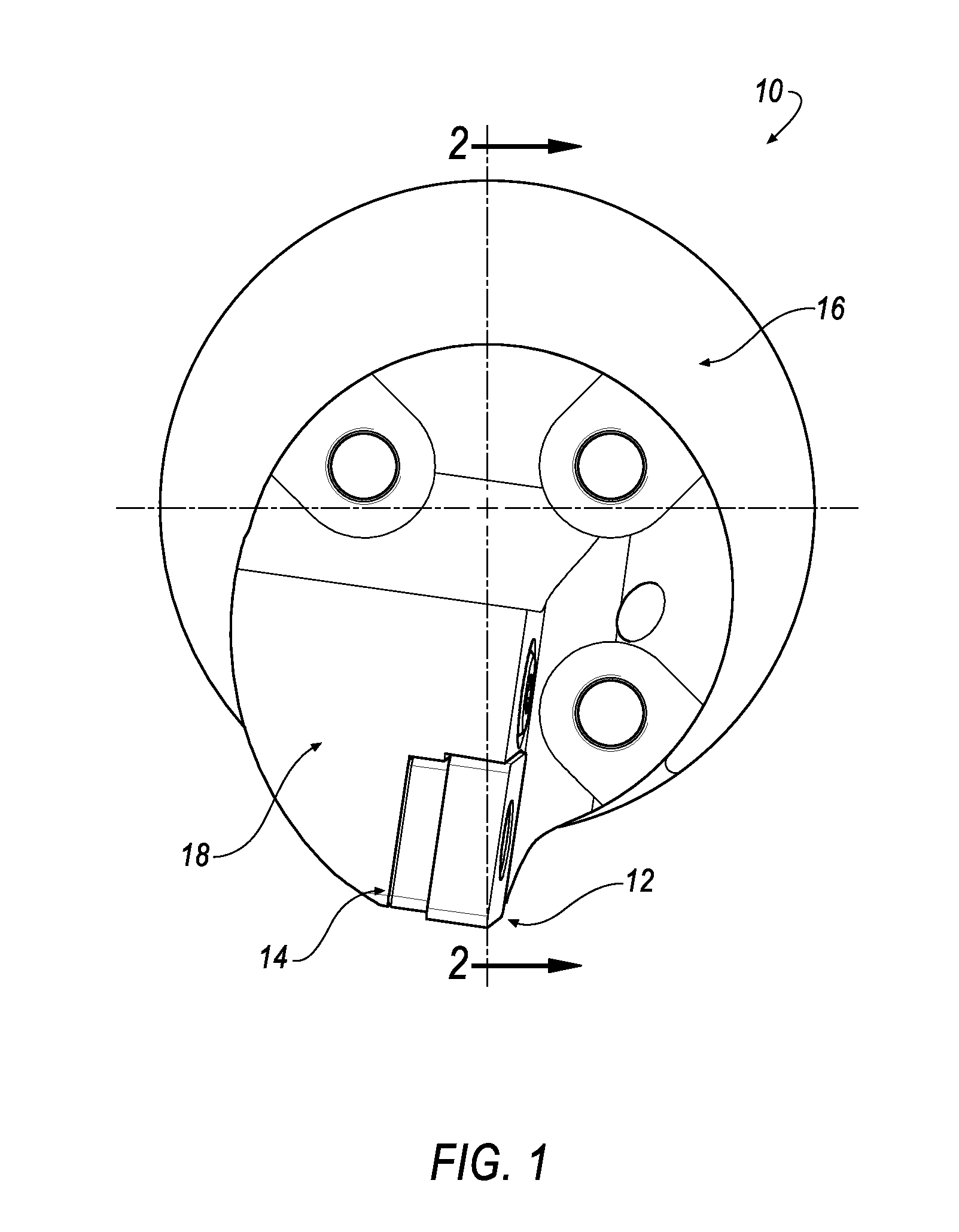
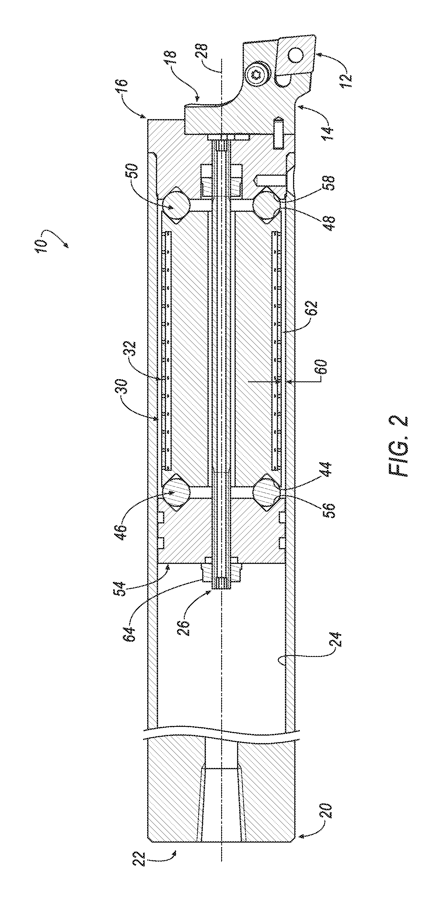
[0017]Referring now to FIGS. 1 and 2, a toolholder 10, such as a boring bar is shown according to an embodiment of the invention. Although the present invention is directed to a boring bar 10 for boring deep holes in work pieces, the principles of the invention can be applied to any toolholder that produces vibrations when cutting a work piece.

[0018]A cutting tool 12, such as a cutting insert, may be mounted in a conventional manner to a head 14 attached to a collar 16 at one end 18 of the boring bar 10. A shank 20 is located at the opposite end 22 of the boring bar 10. The boring bar 10 has a central cavity 24 extending inwardly from the end 18 toward the shank 20. In the illustrated embodiment, the boring bar 10 includes a coolant tube assembly 26 extending along a central, longitudinal axis 28 of the boring bar 10 for providing coolant in the vicinity of the cutting insert 12. It will be appreciated that the coolant tube assembly 26 is optional and can be omitted. For example, th...


PUM


Abstract

A toolholder includes a cutting tool mounted to a head attached to a collar at a first end of the toolholder. A shank is located at a second, opposite end of the toolholder. A central cavity extends inwardly from the first end toward the shank. A viscous fluid inertia mass damper is disposed within the central cavity. The viscous fluid inertia mass damper includes an absorber body having a first end, a second end opposite the first end, a fluid reservoir formed in the damper body for containing a viscous fluid, and a plurality of apertures formed in the damper body for allowing the viscous fluid to flow from the fluid reservoir and through the apertures to suppress vibration of the toolholder. A method for suppressing vibrations in a toolholder is also disclosed.

Description

FIELD OF THE INVENTION[0001]In general, the invention relates to a toolholder and, more particularly, to a toolholder, such as a boring bar, with a tunable viscous fluid inertia mass damper for passive vibration suppression.BACKGROUND OF THE INVENTION[0002]During a metal cutting operation, any vibratory motion between a toolholder and workpiece may lead to undesirable cutting performances such as poor workpiece surface finish and out-of-tolerance finished workpieces. Furthermore, such vibration may cause the toolholder or the machine tool to become damaged.[0003]To reduce these vibrations, the metal removal rate can be decreased. However, this approach interferes with production and only minimally reduces the amount of vibration.[0004]Attempts to eliminate the vibration in a toolholder may also include using a boring bar fabricated from solid carbide. Solid carbide, because of its inherently high density, reduces the amount of chatter and vibration transferred to the boring bar. How...

Claims


Application Information

Patent Timeline
IPC IPC(8): B23B29/02F16F7/10
CPCB23B29/022B23B2260/004B23B2250/16F16F7/1034B23B27/002B23B27/007F16F15/173F16F7/104
Inventor EICHELBERGER, SAMUEL LAWRENCECHEN, SHIFILHO, RUY FROTA DE SOUZAGOLDSMITH, JASON WONKAUFMANN, IGOR
Owner KENNAMETAL INC
Learn More