
Sensor unit for thermal analysis equipment and thermal analysis equipment

Inactive Publication Date: 2017-02-16
RIGAKU CORP
View PDF7 Cites 1 Cited by
  • Summary
  • Abstract
  • Description
  • Claims
  • Application Information

AI Technical Summary

Benefits of technology

The present invention aims to improve the precision of temperature measurement in a multi-pair thermocouple by reducing the dispersion of electromotive forces in individual thermocouples. This is achieved by thermally uniformizing the temperature of the base portion where reference contact points of the thermocouples are arranged.

Problems solved by technology

Accordingly, the temperature is liable to be non-uniform at some places in the base portion of the heat-sensitive member.
However, when the linear expansion coefficient is greatly different between the heat-sensitive member and the thermally uniformizing member in the construction that the thermally uniformizing member is adhesively attached to the base portion of the heat-sensitive member, the degree of thermal expansion caused by heating is different between the members, so that stress may occur between the members, resulting in damage of these members.

Method used


Image

  • Sensor unit for thermal analysis equipment and thermal analysis equipment
  • Sensor unit for thermal analysis equipment and thermal analysis equipment
  • Sensor unit for thermal analysis equipment and thermal analysis equipment

Examples


Embodiment Construction

[0030]An embodiment according to the present invention will be described hereunder with reference to the accompanying drawings.

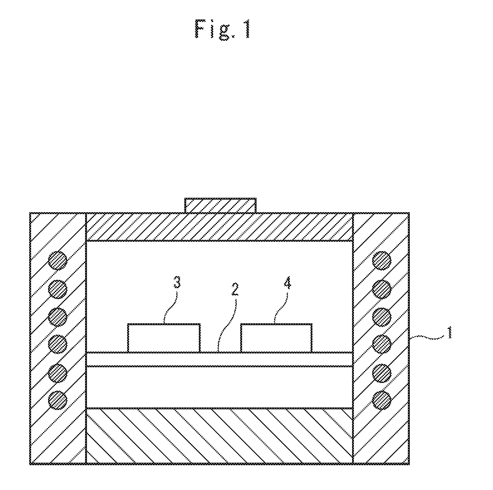
[0031]FIG. 1 is a schematic diagram showing the structure of thermal analysis equipment according to an embodiment of the present invention.

[0032]The thermal analysis equipment shown in FIG. 1 is also referred to as DSC (Differential Scanning Calorimeter), and has a function of measuring the temperature difference between a measurement sample and a reference sample as a function of temperature or time while changing the temperature of the measurement sample and the reference sample according to a certain temperature program.

[0033]The thermal analysis equipment shown in FIG. 1 is configured so that a sensor unit 2 is disposed in a heating furnace 1, and a measurement sample container 3 and a reference sample container 4 are arranged on the upper surface of the sensor unit 2. The measurement sample in the measurement sample container 3 and the reference sample...


PUM


Abstract

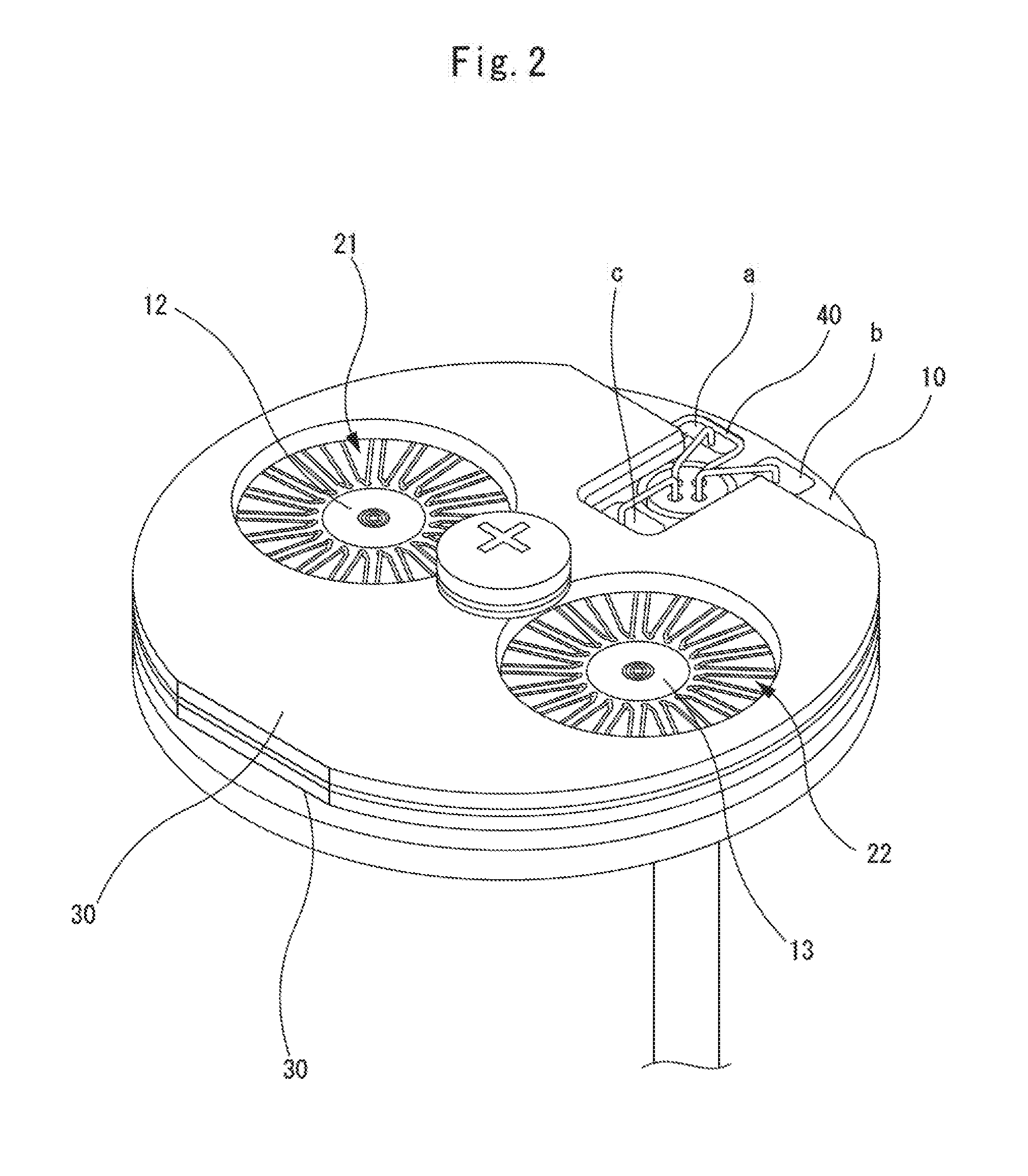
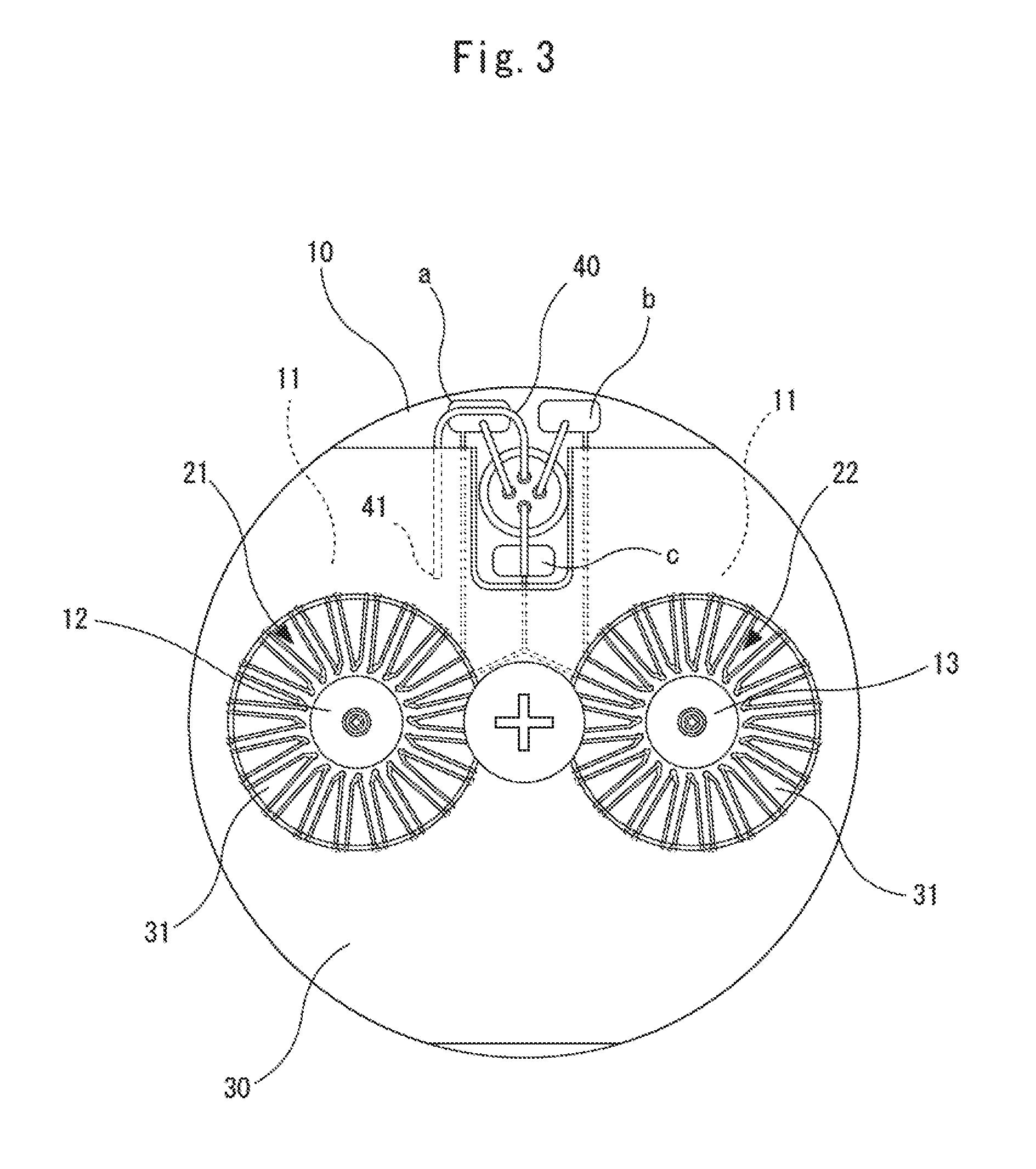
First and second multi-pair thermocouples (21, 22) are formed on the upper surface of a heat-sensitive member (10), and a thermally uniformizing member (30) is adhesively attached to a base portion (11) of the heat-sensitive member (10). The thermally uniformizing member (30) is formed of a heat-resistant and electrically insulating material having a higher thermal conductivity than the heat-sensitive member (10) and a linear expansion coefficient approximate to the linear expansion coefficient of the heat-sensitive member (10). For example, the heat-sensitive member (10) is formed of mullite, and the thermally uniformizing member (30) is formed of aluminum nitride, whereby damage caused by thermal expansion can be prevented and at the same time the base portion (11) of the heat-sensitive member (10) can be thermally uniformalized.

Description

FIELD OF THE INVENTION[0001]The present invention relates to thermal analysis equipment for detecting the temperature difference between a measurement sample and a reference sample, and a sensor unit installed in the same.BACKGROUND OF THE INVENTION[0002]A temperature difference sensor having a pair of thermocouples has been conventionally used for thermal analysis equipment such as DTA (Differential Thermal Analyzer) DSC (Differential Scanning calorimeter) or the like. Such a temperature difference sensor detects the temperature of a measurement sample and the temperature of a reference sample by the respective thermocouples, and outputs the temperature difference between the measurement sample and the reference sample.[0003]Furthermore there has been recently proposed a temperature difference sensor which is configured to detect each of the temperature of a measurement sample and the temperature of a reference sample by using a thermocouple called as a multi-pair thermocouple to e...

Claims


Application Information

Patent Timeline
IPC IPC(8): G01N25/48
CPCG01N25/486G01N25/4866G01K3/08G01K7/02
Inventor NORITAKE, KOICHIRO
Owner RIGAKU CORP
Learn More