
Continuous boron nitride nanotube fibers

Active Publication Date: 2017-02-16
BNNT
View PDF3 Cites 5 Cited by
  • Summary
  • Abstract
  • Description
  • Claims
  • Application Information

AI Technical Summary

Benefits of technology

[0006]What is needed are apparatus, systems, and methods for the continuous pro

Problems solved by technology

Most contemporary BNNT synthesis methods have severe shortcomings, including one or more of having low yield, short tubes, discontinuous production, poor crystallinity (i.e., many defects in molecular structure), and poor al

Method used


Image

  • Continuous boron nitride nanotube fibers
  • Continuous boron nitride nanotube fibers
  • Continuous boron nitride nanotube fibers

Examples


Example

[0034]The following description is of the best currently contemplated mode of carrying out exemplary embodiments of the present approach. The description is not to be taken in a limiting sense, and is made merely for the purpose of illustrating the general principles of the invention.

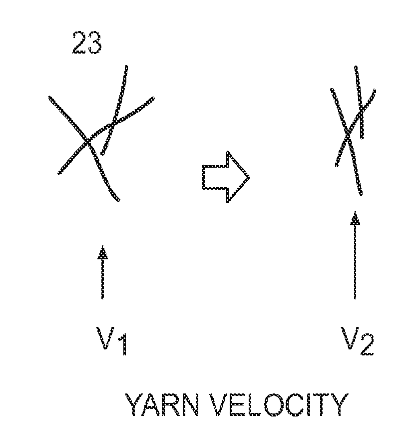
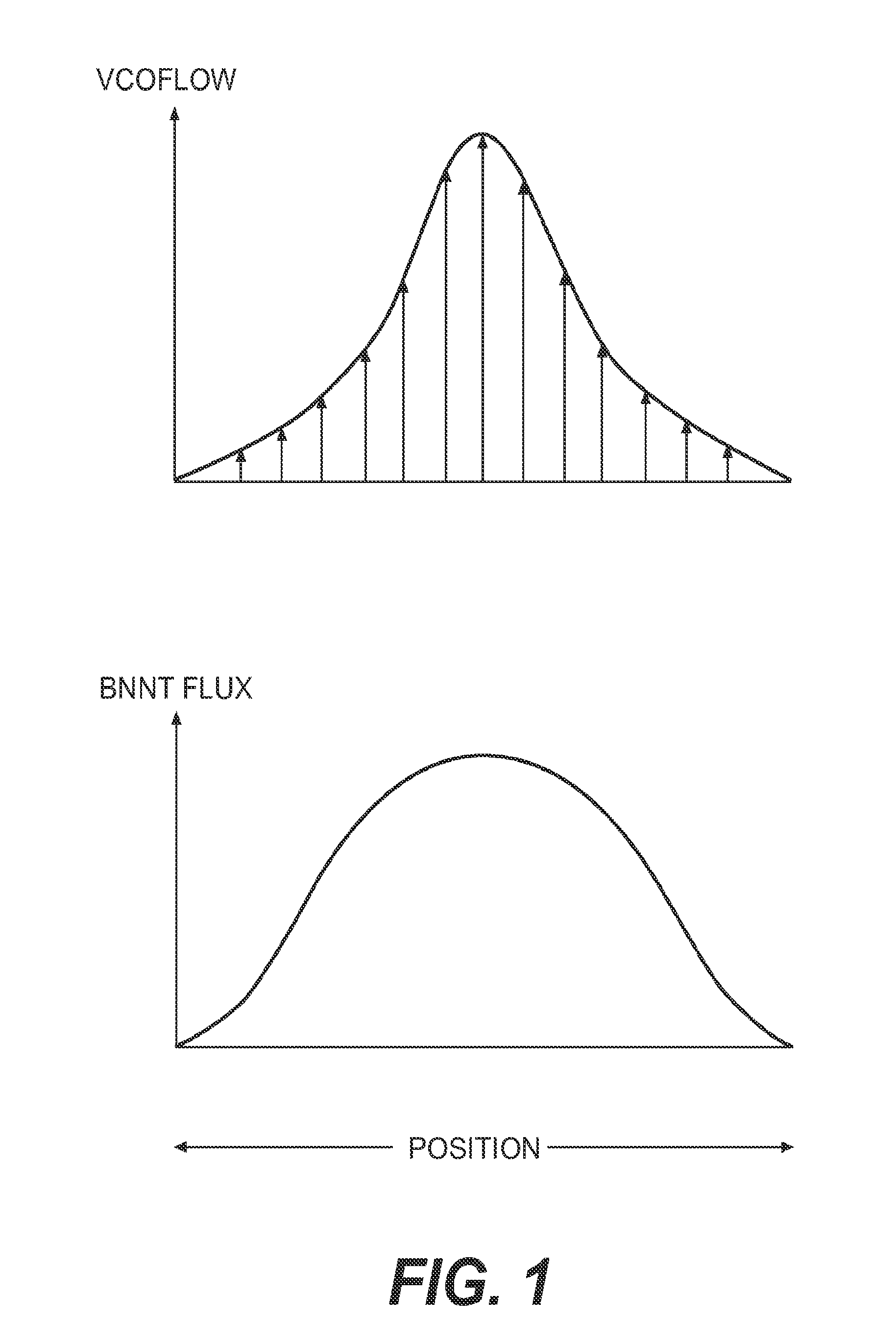
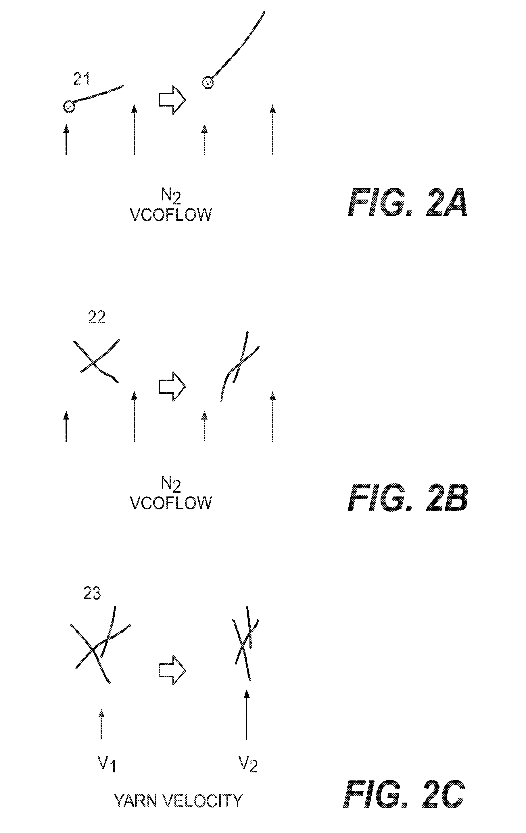
[0035]Described herein are processes and apparatus for producing continuous fibers and strands of BNNT, and in particular BNNT fibers and BNNT strands having good fiber alignment, as well as BNNT yarns. Generally, BNNTs may be formed in a self-assembly region under nitrogen gas. BNNT fiber shear alignment may be enhanced by making adjustments to the velocity distribution of the nitrogen gas, and / or by making adjustments to the BNNT self-assembly region flux distribution, as discussed below.

[0036]The formation of BNNTs is fundamentally different than the formation of CNTs. Synthesis of CNTs typically requires a chemical catalyst, such as a metal catalyst. Unlike the production of CNTs, embodiments for pr...


PUM


Abstract

Described herein are apparatus, systems, and methods for the continuous production of BNNT fibers, BNNT strands and BNNT initial yarns having few defects and good alignment. BNNTs may be formed by thermally exciting a boron feedstock in a chamber in the presence of pressurized nitrogen. BNNTs are encouraged to self-assemble into aligned BNNT fibers in a growth zone, and form BNNT strands and BNNT initial yarns, through various combinations of nitrogen gas flow direction and velocities, heat source distribution, temperature gradients, and chamber geometries.

Description

CROSS REFERENCE TO RELATED APPLICATIONS[0001]This application claims the benefit of U.S. provisional patent application No. 61 / 983,674, filed Apr. 24, 2014; U.S. provisional patent application No. 62 / 101,318, filed Jan. 1, 2015; and U.S. provisional patent application No. 62 / 101,323, filed Jan. 8, 2015.STATEMENT REGARDING GOVERNMENT SUPPORT[0002]None.FIELD[0003]The present disclosure generally relates to the continuous formation of boron nitride nanotube (BNNT) fibers, BNNT strands, and BNNT yarns.BACKGROUND[0004]Generally, BNNT structures may be formed by thermally exciting a boron feedstock in a chamber in the presence of nitrogen gas at an elevated pressure. Unlike carbon nanotubes (CNTs), U.S. Pat. No. 8,206,674 to Smith et al., incorporated by reference in its entirety, indicates that BNNTs form without the presence of chemical catalysts, and preferably at elevated pressures of about 2 atm to about 250 atm. CNTs, on the other hand, typically require the presence of chemical cat...

Claims


Application Information

Patent Timeline
IPC IPC(8): C01B21/064H01L23/373D01F9/08
CPCC01B21/0641D01F9/08H01L23/3731Y10S977/891B82Y40/00B82Y30/00Y10S977/762C01P2004/13H01L23/373H01L21/00H01L2924/0002C01B35/146H01L2924/00D02G3/02D02G3/26H01L21/02606
Inventor SMITH, MICHAEL W.STEVENS, JONATHAN C.JORDAN, KEVIN C.WHITNEY, R. ROY
Owner BNNT
Learn More