
Method and apparatus for aligning coupled digital print engines

Inactive Publication Date: 2010-12-30
EASTMAN KODAK CO
View PDF15 Cites 1 Cited by
  • Summary
  • Abstract
  • Description
  • Claims
  • Application Information

AI Technical Summary

Benefits of technology

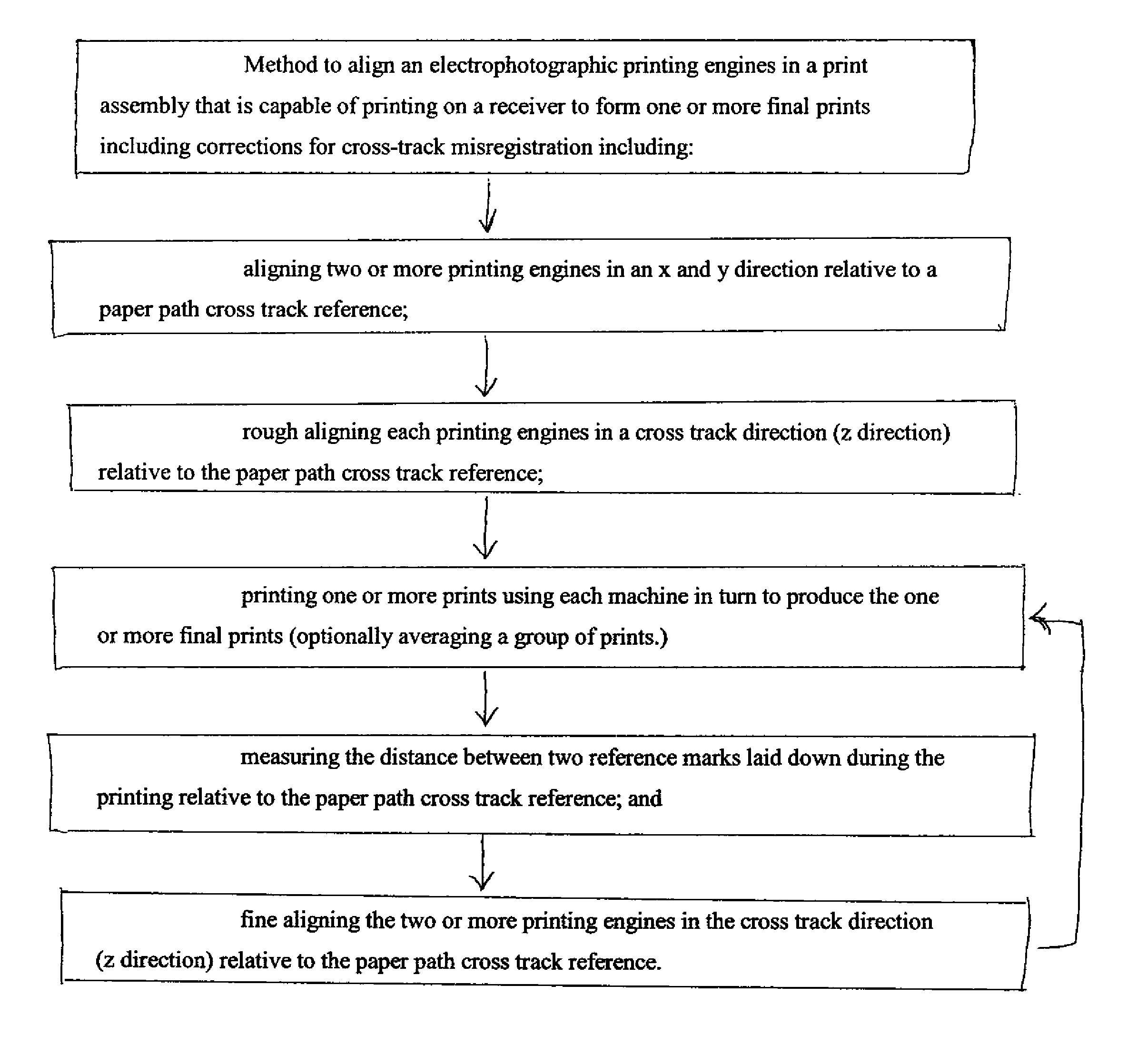
[0010]According to this invention, an adjustment method aligns printing engines in a print assembly that is capable of printing on a receiver to form one or more final prints and includes corrections for cross-track misregistration. These adjustments are made in one embodiment by aligning two or more printing engines in an x and y direction relative to a paper path cross track reference and then aligning each printing engines in a cross track direction (z direction) relative to the paper path cross track reference based on measurements in the cross track direction (z direction) relative to the paper p

Problems solved by technology

However, the doubling of throughput speed is mainly unachievable without a) purchasing a second reproduction apparatus with throughput identical to the first so that the two machines may be run in parallel, or without b) replacing the first reproduction apparatus with a radically redesigned print engine having double the speed.
Both options are very expensive and often with regard to option (b), not possible.
Unfortunately, such a system tends to be susceptible to increasing registration errors during each successive image frame during the photoreceptor revolution.
Furthermore, given the large inertia of the high-speed rotating polygon assembly, it is difficult to make significant adjustments to the speed of the polygon assembly in the relatively short time frame of a single photoreceptor revolution.
This can limit the response of the '856 system on a per revolution basis, and make it even more difficult, if not impossible, to adjust on a more frequent basis.
The quality of images produced on different print engines can be found to be objectionable if produced on different print engines even if the print engines are nominally the same, e.g. the same model produced by the same manufacturer.
Specifically, the reflection density and the contrast of the prints need to closely match or the prints will be found to be objectionable to a customer.

Method used


Image

  • Method and apparatus for aligning coupled digital print engines
  • Method and apparatus for aligning coupled digital print engines
  • Method and apparatus for aligning coupled digital print engines

Examples


Embodiment Construction

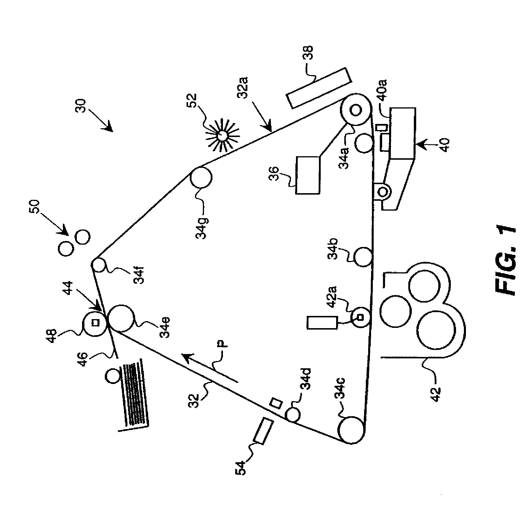
[0020]FIG. 1 schematically illustrates an embodiment of an electrophotographic print engine 30. The print engine 30 has a movable recording member such as a photoreceptive belt 32, which is entrained about a plurality of rollers or other supports 34a through 34g. The photoreceptive belt 32 may be more generally referred-to as a primary imaging member (PIM) 32. A primary imaging member (PIM) 32 may be any charge carrying substrate which may be selectively charged or discharged by a variety of methods including, but not limited to corona charging / discharging, gated corona charging / discharging, charge roller charging / discharging, ion writer charging, light discharging, heat discharging, and time discharging.

[0021]One or more of the rollers 34a-34g are driven by a motor 36 to advance the PIM 32. Motor 36 preferably advances the PIM 32 at a high speed, such as 20 inches per second or higher, in the direction indicated by arrow P, past a series of workstations of the print engine 30, alth...


PUM


Abstract

The adjustment method aligns printing engines in a print assembly that is capable of printing on a receiver to form one or more final prints and includes corrections for cross-track misregistration. These adjustments are made in one embodiment by aligning two or more printing engines in an x and y direction relative to a paper path cross track reference and then aligning each printing engines in a cross track direction (z direction) relative to the paper path cross track reference based on measurements in the cross track direction (z direction) relative to the paper path cross track reference.

Description

FIELD OF THE INVENTION[0001]This invention relates to a printing system comprising a plurality of print engines, at least one of which is a digital print engine using electrophotographic technology.BACKGROUND OF THE INVENTION[0002]In typical commercial reproduction apparatus (electrographic copier / duplicators, printers, or the like), a latent image charge pattern is formed on a primary imaging member (PIM) such as a photoreceptor used in an electrophotographic printing apparatus. While the latent image can be formed on a dielectric PIM by depositing charge directly corresponding to the latent image, it is more common to first uniformly charge a photoreceptive PIM member. The latent image is then formed by area-wise exposing the PIM in a manner corresponding to the image to be printed. The latent image is rendered visible by bringing the primary imaging member into close proximity to a development station. A typical development station may include a cylindrical magnetic core and a co...

Claims


Application Information

Patent Timeline
IPC IPC(8): G03G15/00
CPCG03G21/16G03G2221/1678G03G2221/1654G03G2215/00021
Inventor PITAS, JEFFREY A.RAPKIN, ALAN E.DOBBERTIN, MICHAEL T.
Owner EASTMAN KODAK CO
Learn More