
Mount for two frameless spectacle lenses

Inactive Publication Date: 2006-03-21
SILHOUETTE INT SCHMIED
View PDF10 Cites 0 Cited by
  • Summary
  • Abstract
  • Description
  • Claims
  • Application Information

AI Technical Summary

Benefits of technology

[0006]The invention is thus based on the object of avoiding these deficiencies and to provide a fastener device for two frameless lenses of the kind mentioned above in such a way that a durable, sufficiently sturdy adhesive connection can be achieved between the lenses and the nose support without having to cover the edge sections of the lenses.
[0008]Since as a result of these measures the lenses are not connected directly with the supporting parts but through a flexurally soft support, the flexurally soft support provides a compensation for the tensions from different thermal expansions of the lenses and the supporting parts and from mechanical stresses of the lenses, so that the adhesive layers which are relatively brittle after the curing can be kept substantially free from tensions. Despite the flexurally soft support, a favorable dimensional stability for the fastener device of the lenses is ensured through the supporting parts which can be provided with a sufficiently flexurally rigid design. Since the gluing of the lenses occurs along a face-side circumferential section, the free glass surface area is not restricted by the fastener device. An additional factor is that the adherence of the adhesive layer to the lenses cannot be impaired by the usual coatings of the lenses because the face-sides of the lenses do not have any such coatings.
[0009]The flexurally soft supports of the supporting parts not only constitute a durably, sufficiently sturdy fastening of the lenses by gluing, but also allow swiveling out the lenses from a predetermined basic position within the scope of the elastic properties of the support, which can be used advantageously for cleaning the glasses for example. In order to enable a sufficient swiveling angle without overloading the supports or the adhesive layers, the flexurally soft supports can be provided with a capacity to be lifted off at least in sections from the supporting parts in the glued region. The lack of connection of the supports with the supporting parts in the connecting region with the lenses allows a further deformation of the supports with the effect that the swiveling range of the lenses relative to the supporting parts is increased.
[0010]Especially simple constructional conditions are obtained when the flexurally soft supports form nose-pieces of the nose support, because in this case the flexurally soft nose-pieces which must be provided anyway can form a bonding layer required for an advantageous adhesive connection for the purpose of compensating tensions, so that separate supports can be omitted for this purpose.
[0013]Although the coupling set-offs which cooperate with the latching recesses for the formation of a plug-in coupling can be provided on different coupling sides, especially advantageous constructional conditions are obtained when the coupling parts consist of bridge-like coupling set-offs on the nose-piece of the nose support and the lens insert, which set-offs engage in oblong-shaped latching recesses of the spectacles. A fixing of the legs of the nose-piece relative to the spectacles which is protected against twisting is achieved via the bridge-like coupling set-offs and the oblong-shaped latching recesses. The latching recesses can be arranged, depending on the configuration of the spectacles, on an integral lens, on two spectacle lenses or on a frame for the lenses. In order to provide simple constructional conditions in this connection, the coupling parts which are associated with the nose-piece of the lens insert can be formed by supporting parts for the optical spectacle lenses.
[0014]The flexurally soft bonding layer formed by the nose-piece for the adhesive connection between the lenses and the supporting parts of the lens insert supports swiveling out the optical lenses from the spectacles without having to remove the lens insert. The deflection of the optical lenses against the elastic restoring force of the flexurally soft nose-piece which carries the same may lead to the optical lenses of the lens insert striking against the lenses of the spectacles per se. In order to avoid the likelihood of damage to the surface of the lenses, the optical lenses of the lens insert may carry spacers on their front side facing the spectacles in the region of a circumferential section opposite of the nose-piece, which spacer effectively prevents the lenses of the lens insert from striking against the lenses of the spectacles. Said spacers can also be used for better alignment of the optical lenses relative to the spectacles of sunglasses for example when during the insert of the lens insert into the sunglasses via the flexurally soft nose-piece a pretension is produced which presses the optical lenses with the spacers against the lenses of the sunglasses.

Problems solved by technology

The disadvantageous aspect in such known spectacles which can optionally be equipped with a nose support or an optical lens insert is that the lens insert requires a frame carrying the optical lenses, which not only increases the weight of the optical lens insert but also makes the lens insert visible through the spectacles.
This means that a complex nose-piece with a projecting, flexurally rigid fastening set-off for the lens insert is required, which necessitates separate nose-pieces for the sunglasses without an optical lens insert.
The disadvantageous aspect in said known glued connection is first that the bridges cover an edge section of the lenses.
Moreover, tensions occur in the adhesive layer as a result of different thermal expansions of the lenses and the nose support, which can lead to a detachment of the adhesive connection.
As a result of the use of suitable, comparatively brittle adhesive materials there is also a considerable likelihood of breakage for the lenses when they are moved relative to the nose support because the nose support requires a certain dimensional stability.

Method used


Image

  • Mount for two frameless spectacle lenses
  • Mount for two frameless spectacle lenses
  • Mount for two frameless spectacle lenses

Examples


Embodiment Construction

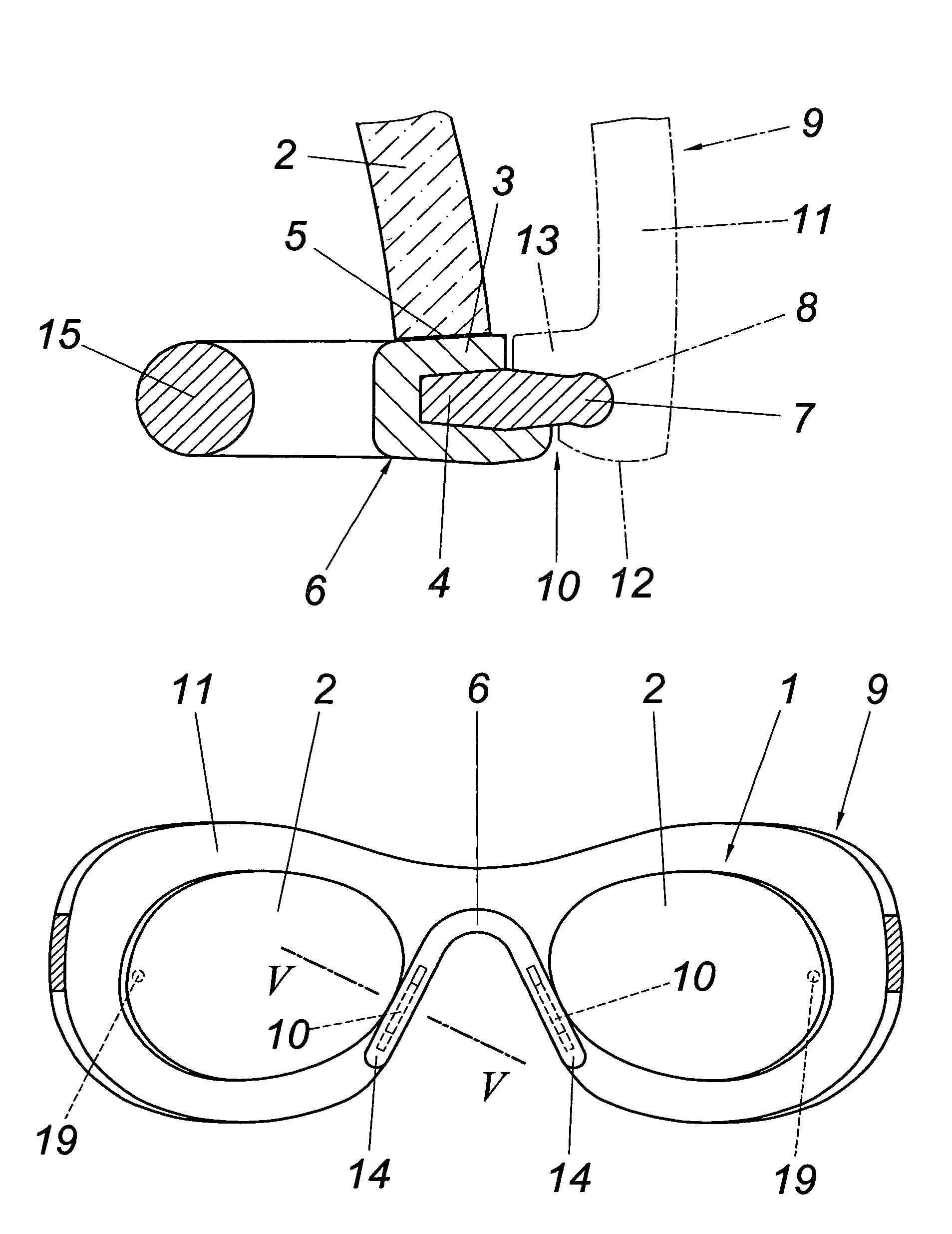
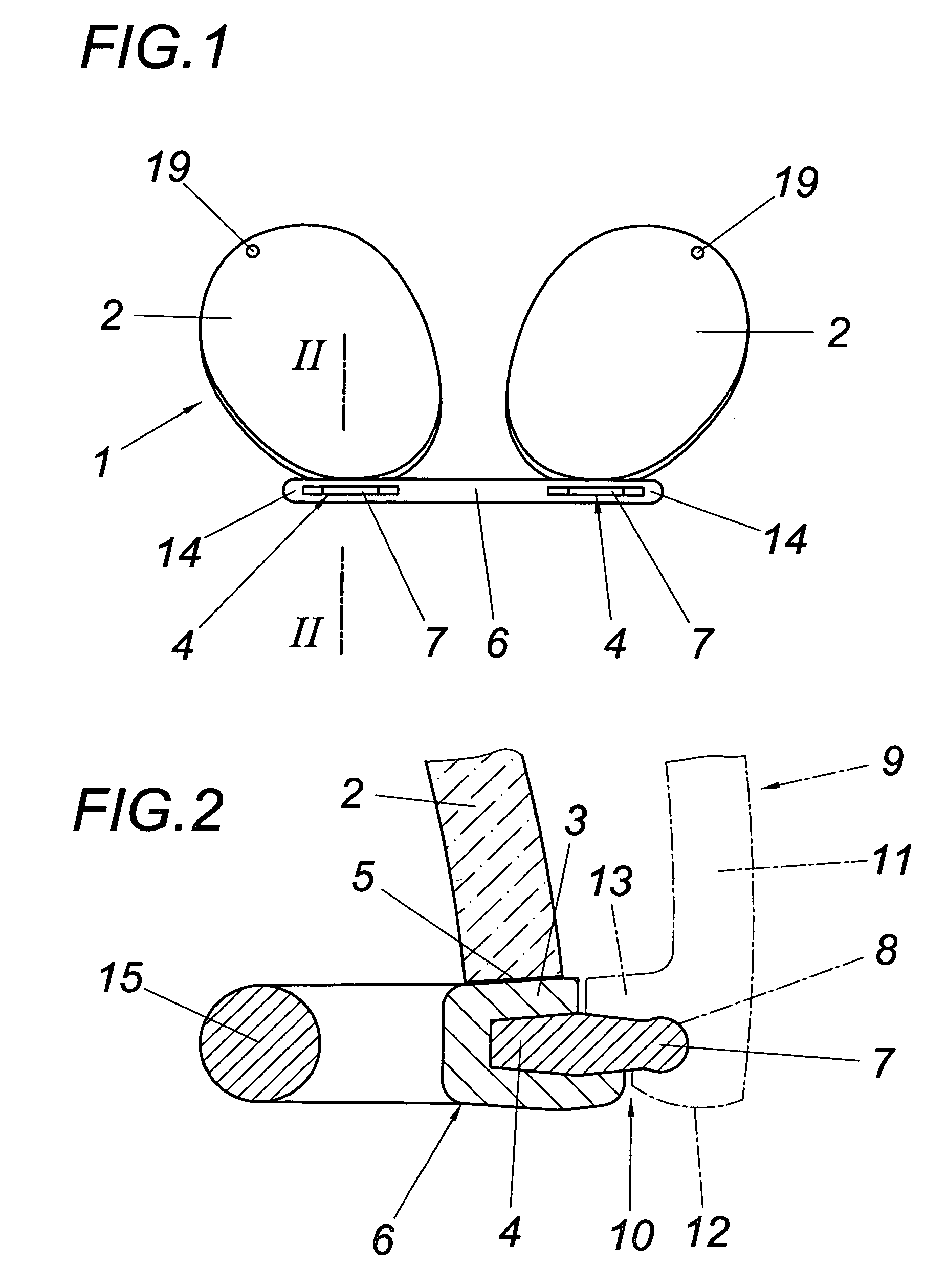
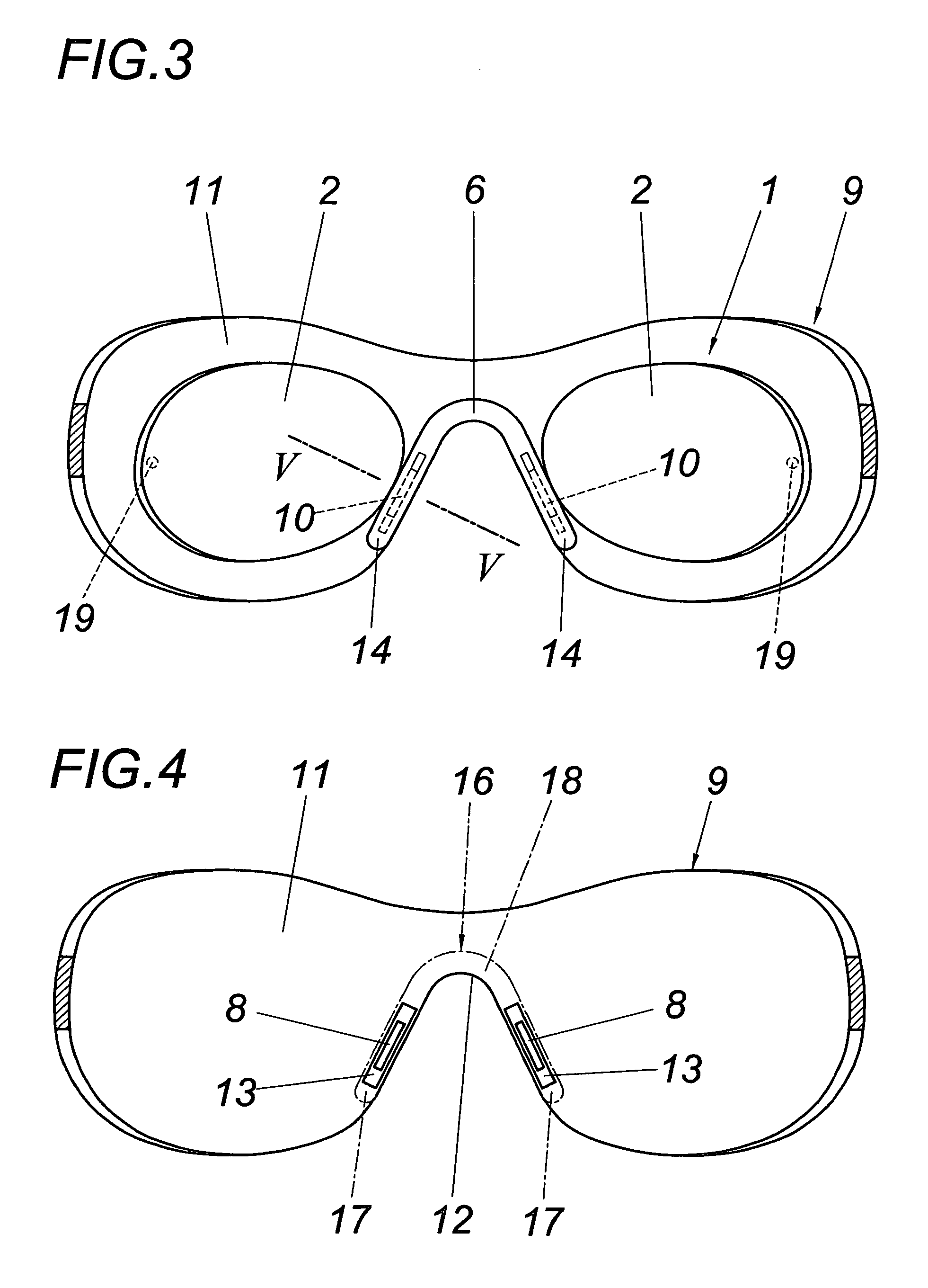
[0021]The lens insert 1 consists according to FIGS. 1 and 2 of two optical lenses 2 which are fastened to supporting parts 4 which are provided with a flexurally soft support 3, this being through an adhesive layer 5 between the support 3, which support is made of plastic and is preferably injected onto the supporting parts 4, and a circumferential section of the face side of the lenses 2, as is shown in particular in FIG. 2. The supports 3 of the supporting parts 4 are mutually integrally connected to form a flexurally soft nose-piece 6 having a straight progress. The substantially flexurally rigid supporting parts 4 form bridge-shaped coupling parts 7 which latch into oblong-shaped latching recesses 8 of spectacles 9 and produce with the same a plug-in coupling 10 for fastening the optical lens insert.

[0022]FIG. 4 shows such spectacles 9 in closer detail. It comprises an integral sunshield 11 which is used for protection against the sun and is provided with a nose recess 12. Along...


PUM


Abstract

A fastener device for two frameless spectacle lenses (2) comprises a nose support provided between the spectacle lenses (2) and supporting parts (4) provided in the region of the nose support onto which the spectacle lenses (2) are glued. In order to provide advantageous bonding conditions it is proposed that the supporting parts (4) comprise flexurally soft supports (3) made of plastic, onto which the spectacle lenses (2) are glued along a face-side circumferential section.

Description

CROSS REFERENCE TO RELATED APPLICATIONS[0001]Applicant claims priority under 35 U.S.C. §119 of Austrian Application No. A713 / 2001 filed on 3 May 2001. Applicant also claims priority under 35 U.S.C. §365 of PCT / AT02 / 00135 filed on 3 May 2002. The international application under PCT article 21(2) was not published in English.FIELD OF THE INVENTION[0002]The invention relates to a fastener device for two frameless spectacle lenses with a nose support disposed between the spectacle lenses and with supporting parts disposed in the region of the nose support onto which the spectacle lenses are glued.DESCRIPTION OF THE PRIOR ART[0003]In order to equip sunglasses in an optional fashion with an optical lens insert it is known (DE 34 13 872) to provide a plug-in coupling in the region of the nose saddle of the sunglasses with the help of which an optical lens insert can be connected, such that the nose saddle of the frame for the lenses of the optical lens insert is pressed into latching reces...

Claims


Application Information

Patent Timeline
IPC IPC(8): G02C1/00G02C1/02G02C9/00
CPCG02C9/00G02C1/02
Inventor SPINDELBALKER, RUPERT
Owner SILHOUETTE INT SCHMIED
Learn More