Exhaust gas control apparatus and exhaust gas control method for internal combustion engine

a technology of exhaust gas control apparatus and control apparatus, which is applied in the direction of electrical control, machine/engine, exhaust treatment electric control, etc., can solve the problems of increasing the ammonia desorbed from the catalyst, the inability to perform appropriate nox removal, and the ammonia slip is likely to occur, so as to achieve accurate calculation and flow rate. , accurate calculation

Inactive Publication Date: 2017-02-09
TOYOTA JIDOSHA KK
View PDF6 Cites 4 Cited by
  • Summary
  • Abstract
  • Description
  • Claims
  • Application Information

AI Technical Summary

Benefits of technology

[0014]The temperature of the catalyst is raised by heat transfer from the exhaust gas. The amount of the heat that is transferred from the exhaust gas to the catalyst decreases as the flow rate of the exhaust gas flowing into the catalyst decreases. Accordingly, when the temperature of the catalyst is calculated with the effect of the exhaust gas flow rate taken into account, the temperature of the catalyst can be more accurately calculated. As a result, the integrated value of the temperature of the catalyst can also be more accurately calculated.
[0015]According to the configuration described above, the temperature of the exhaust gas flowing into the catalyst and the flow rate of the exhaust gas flowing into the catalyst are acquired. Then, the acquired exhaust gas temperature is corrected to decrease as the acquired exhaust gas flow rate decreases and the corrected temperature is used as the temperature of the catalyst. Accordingly, the temperature of the catalyst that is acquired by the electronic control unit decreases as the flow rate of the exhaust gas decreases. As a result, the integrated value of the catalyst temperature calculated in the initialization processing decreases as the exhaust gas flow rate decreases. During the calculation of the integrated value of the temperature of the catalyst as described above, the effect of the exhaust gas flow rate regarding the amount of the heat transferred from the exhaust gas to the catalyst is taken into account, and thus the integrated value of the temperature of the catalyst can be accurately calculated.

Problems solved by technology

When the amount of the ammonia adsorbed on the catalyst is insufficient, an appropriate NOx removal cannot be performed.
When the ammonia adsorption amount is excessive, an ammonia slip is likely to occur.
When a high-temperature state of the catalyst continues for a long period of time, however, the amount of the ammonia that is desorbed from the catalyst increases, and thus the actual ammonia adsorption amount deviates from the target adsorption amount, which causes error to be accumulated.
In the apparatus that is disclosed in JP 2014-88800 A, an error of the estimated value of the ammonia adsorption amount itself might result in an inaccurate calculation of the deviation described above.
Once a state where the deviation falls short of the predetermined value continues as a result of the inaccurately calculated deviation, a state where the initialization processing is not executed continues, and then the error might increase.
As described above, when a high-temperature state of the catalyst continues for a long period of time, an error between the target adsorption amount and the actual ammonia adsorption amount is accumulated and increased.

Method used


Image

  • Exhaust gas control apparatus and exhaust gas control method for internal combustion engine
  • Exhaust gas control apparatus and exhaust gas control method for internal combustion engine
  • Exhaust gas control apparatus and exhaust gas control method for internal combustion engine

Examples


Embodiment Construction

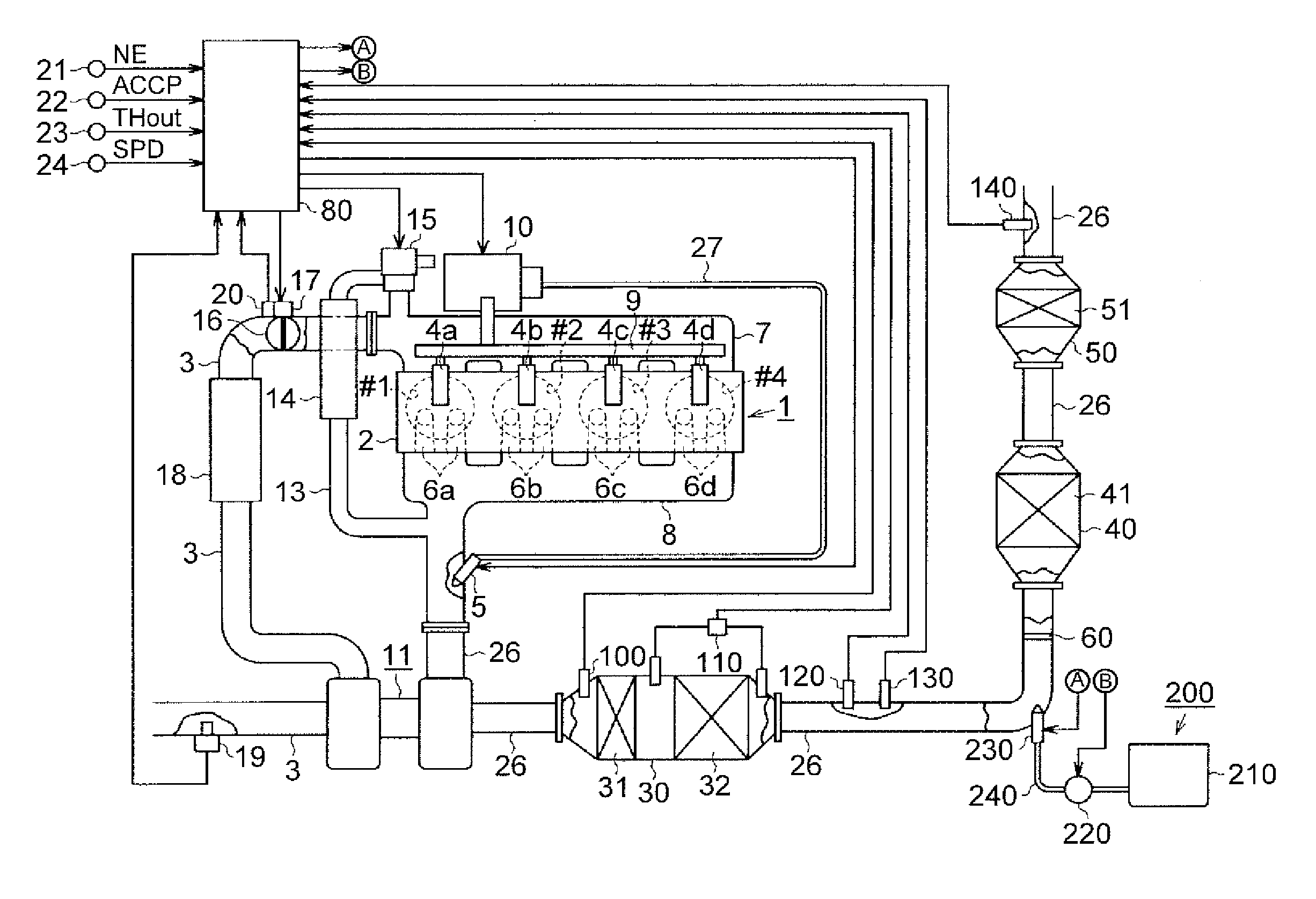
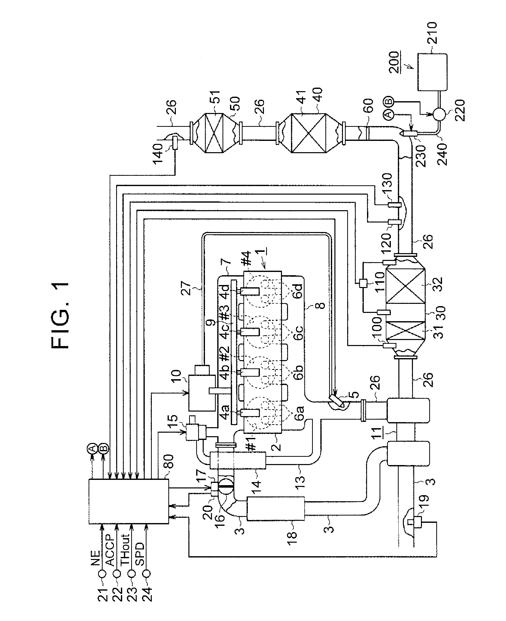
[0030]Hereinafter, a specific embodiment of an exhaust gas control apparatus for an internal combustion engine will be described with reference to FIGS. 1 to 6. FIG. 1 shows a diesel engine (hereinafter, simply referred to as an “engine”) to which the exhaust gas control apparatus according to this embodiment is applied and a peripheral configuration thereof.

[0031]A plurality of cylinders #1 to #4 are disposed in an engine 1. A plurality of fuel injection valves 4a to 4d are disposed in a cylinder head 2 to correspond to the respective cylinders #1 to #4. These fuel injection valves 4a to 4d inject a fuel into combustion chambers of the respective cylinders #1 to #4. An intake port for introducing fresh air into the cylinders and exhaust ports 6a to 6d for discharging combustion gas (exhaust gas) out of the cylinders are disposed in the cylinder head 2 to correspond to the respective cylinders #1 to #4.

[0032]The fuel injection valves 4a to 4d are connected to a common rail 9 that ac...


PUM


Abstract

An exhaust gas control apparatus and method for an engine includes a urea water supply mechanism that adds urea water to exhaust gas, a SCR catalyst that adsorbs ammonia and removes NOx in the exhaust gas by using the adsorbed ammonia, and a control device that controls a urea water addition amount based on a target adsorption amount for the ammonia adsorbed onto the SCR catalyst. The control device executes an integration processing that acquires a temperature of the SCR catalyst at a predetermined cycle and integrates the acquired temperature of the SCR catalyst when equal to or higher than a threshold, and an initialization processing that decreases the amount of the ammonia adsorbed on the SCR catalyst on a condition that an integrated value of the temperature of the SCR catalyst calculated in the integration processing has become equal to or higher than a predetermined value.

Description

INCORPORATION BY REFERENCE[0001]The disclosure of Japanese Patent Application No. 2015-156268 filed on Aug. 6, 2015 including the specification, drawings and abstract is incorporated herein by reference in its entirety.BACKGROUND[0002]1. Technical Field[0003]The disclosure relates to an exhaust gas control system and an exhaust gas control apparatus for an internal combustion engine.[0004]2. Description of Related Art[0005]Japanese Patent Application Publication No. 2014-88800 (JP 2014-88800 A) discloses an internal combustion engine that is provided with a catalyst which removes nitrogen oxide (NOx) in exhaust gas. An adding mechanism that adds urea water to the exhaust gas is disposed in an exhaust passage of the internal combustion engine, and ammonia resulting from the urea water is adsorbed onto the catalyst for the NOx removal. The NOx is reduced and removed by the use of the ammonia that is adsorbed on the catalyst.[0006]When the amount of the ammonia adsorbed on the catalyst...

Claims


Application Information

Patent Timeline
Patent Type & Authority Applications(United States)
IPC IPC(8): F02D41/02F01N3/08F01N11/00F01N3/20
CPCF02D41/0275F01N3/2066F01N3/0814F01N2610/1453F01N3/0842F01N11/002F01N2610/02F01N3/0885F01N3/208F01N9/00F01N2570/18F01N2900/1411F01N2900/1602F01N2900/1622Y02T10/12Y02T10/40F02D41/0235F01N2560/06F01N2570/14
Inventor OTA, HIROHIKO
Owner TOYOTA JIDOSHA KK
Why Eureka
Try Eureka