Method of screen printing
a screen printing and screen technology, applied in the direction of printing, printed circuit, printed circuit manufacturing, etc., can solve the problem of increasing the size of the entire apparatus, and achieve the effect of not increasing the size of the apparatus
- Summary
- Abstract
- Description
- Claims
- Application Information
AI Technical Summary
Benefits of technology
Problems solved by technology
Method used
Image

Examples
first embodiment
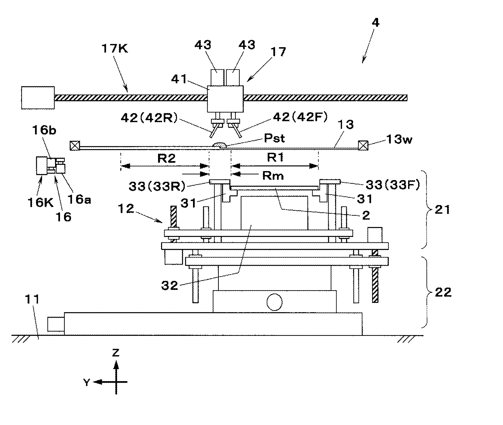
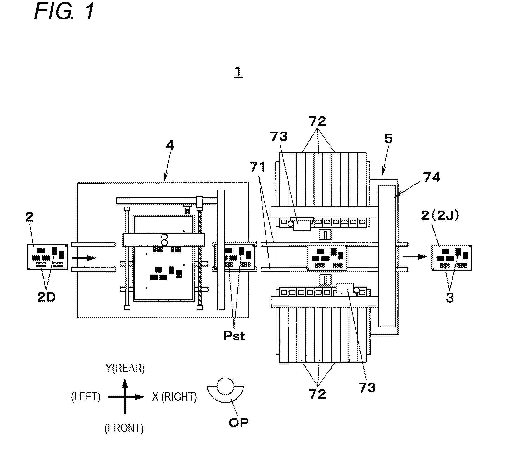
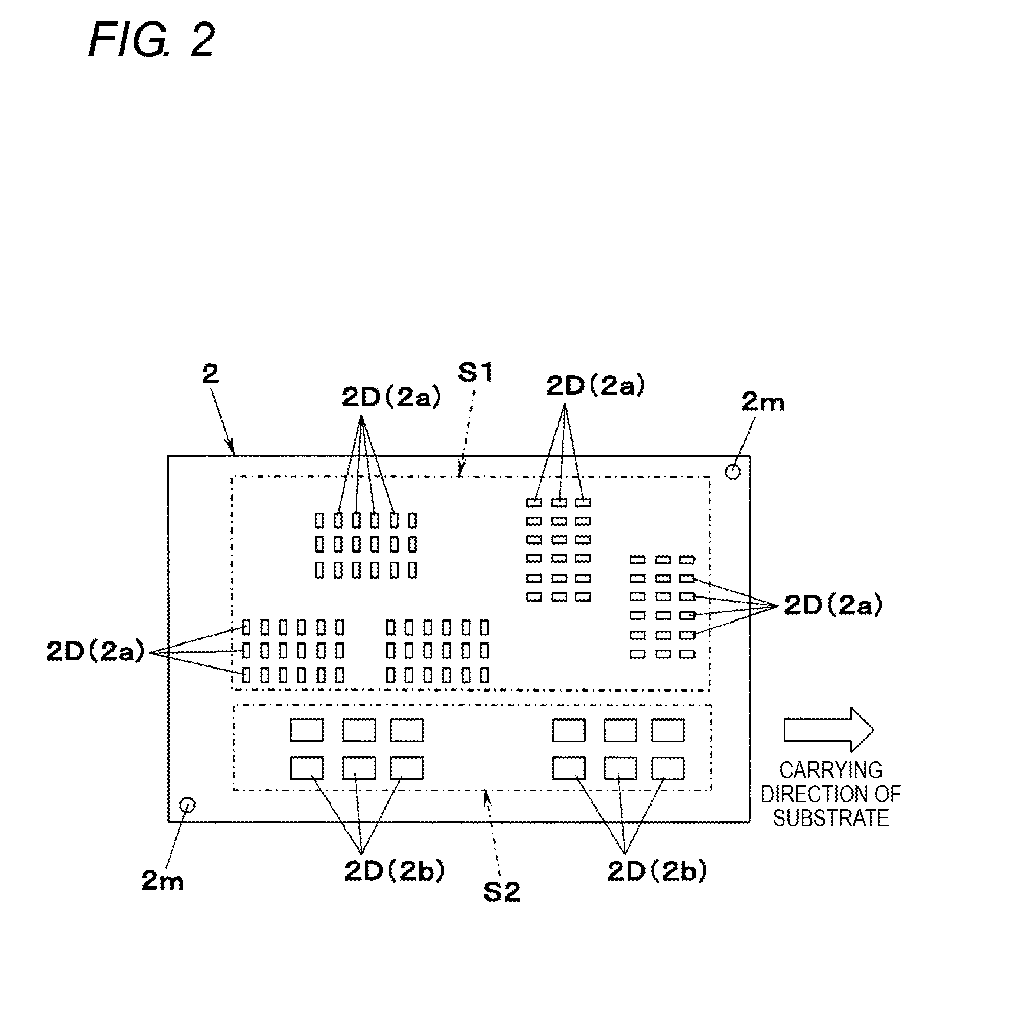
[0035]FIG. 1 illustrates a component mounting line 1 according to a first embodiment of the present invention. The component mounting line 1 mounts a component 3 onto a substrate 2 and manufactures a mounted substrate 2J, and is provided with a screen printing apparatus 4 and a component mounting apparatus 5 which is disposed on a downstream process side thereof. The screen printing apparatus 4 receives the substrate 2 which is input from an upstream process side, screen-prints a paste Pst on an electrode 2D of the substrate 2, and delivers the substrate 2 to the component mounting apparatus 5. The component mounting apparatus 5 receives the substrate 2 from the screen printing apparatus 4, and mounts the component 3 onto the electrode 2D on which the paste Pst is printed. In the following description, for convenience, a horizontal direction of the component mounting line 1 when viewed from an operator OP is considered as an X-axis direction, and the substrate 2 flows from a left si...
second embodiment
[0059]FIG. 20 illustrates the screen printing apparatus 4 according to a second embodiment of the present invention. The screen printing apparatus 4 according to the second embodiment has substantially the same operation during the screen printing as that of the screen printing apparatus 4 according to the first embodiment, but the configurations of the mask 13 are different from each other. In other words, the mask 13 of the screen printing apparatus 4 according to the second embodiment is provided with an inclination surface 13S in which the upper surface of the intermediate region Rm in the mask 13 according to the first embodiment connects the upper surface of the front masking region R1 and the upper surface of the rear masking region R2 to each other (refer to FIG. 21). Accordingly, since the upper surface of the front masking region R1 and the upper surface of the rear masking region R2 are smoothly linked to each other, and the movement of the paste Pst on the mask 13 become...
third embodiment
[0060]FIG. 22 illustrates the screen printing apparatus 4 according to a third embodiment of the present invention. The screen printing apparatus 4 according to the third embodiment, also has substantially the same operation during the screen printing as that of the screen printing apparatus 4 according to the first embodiment, but the configurations of the mask 13 are different from each other. In other words, in the screen printing apparatus 4 according to the third embodiment, the upper surface of the front masking region R1 and the upper surface of the rear masking region R2 are the same plane, and the height of the upper surface of the front masking region R1 and the height of the upper surface of the rear masking region R2 are equivalent to each other (refer to FIG. 23). For this reason, similar to a case of the second embodiment, the movement of the paste Pst on the mask 13 becomes smooth, and a scraping operation of the paste Pst becomes smooth.
[0061]As can be ascertained fr...
PUM
 Abstract
Description
Claims
Application Information
 - R&D
- Intellectual Property
- Life Sciences
- Materials
- Tech Scout
- Unparalleled Data Quality
- Higher Quality Content
- 60% Fewer Hallucinations
Browse by: Latest US Patents, China's latest patents, Technical Efficacy Thesaurus, Application Domain, Technology Topic, Popular Technical Reports.
© 2025 PatSnap. All rights reserved.Legal|Privacy policy|Modern Slavery Act Transparency Statement|Sitemap|About US| Contact US: help@patsnap.com