
Method and apparatus for producing crystalline cladding and crystalline core optical fibers

Active Publication Date: 2017-02-02
PENN STATE RES FOUND +1
View PDF1 Cites 15 Cited by
  • Summary
  • Abstract
  • Description
  • Claims
  • Application Information

AI Technical Summary

Benefits of technology

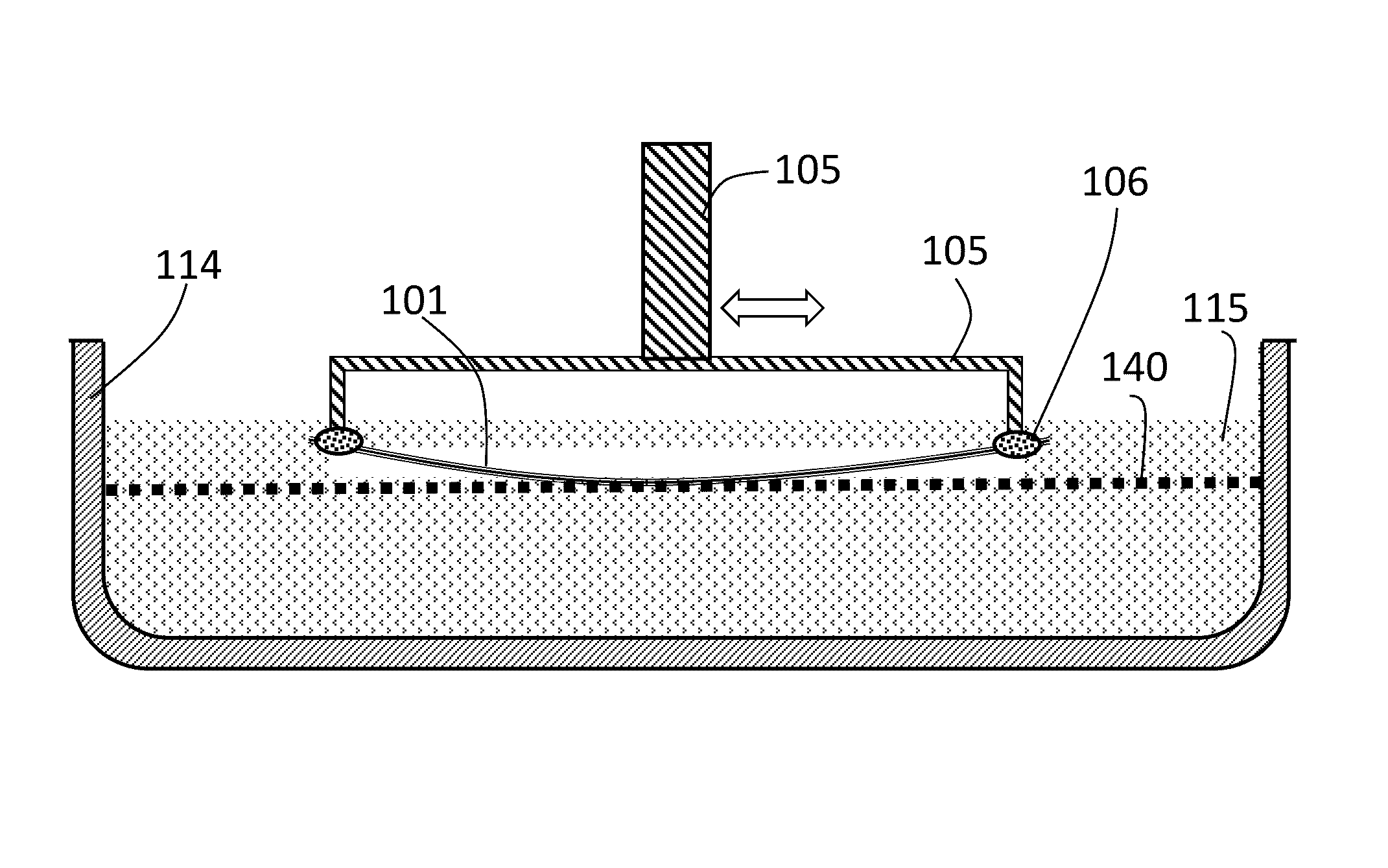
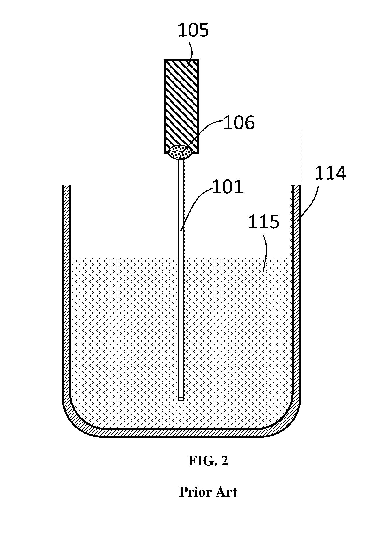
The patent text describes methods for preparing high quality crystalline cladding and crystalline core optical fibers using liquid phase epitaxy (LPE). The first step involves reducing the diameter of the fiber core preform and then growing a crystalline cladding layer on top using a super-saturated LPE flux to control the refractive index. To prevent thermal stresses from damaging the fiber during this process, the fiber core is held in a molten LPE solution using various holding methods such as pre-bent holding or one-end firm holding. Another embodiment of the patent describes a unique hot isostatic pressing (HIP) method for transforming polycrystalline cladding into a single crystalline cladding through solid state conversion. The technical effects of these methods include precise control of mode propagation, improved fiber quality, and better mechanical strength.

Problems solved by technology

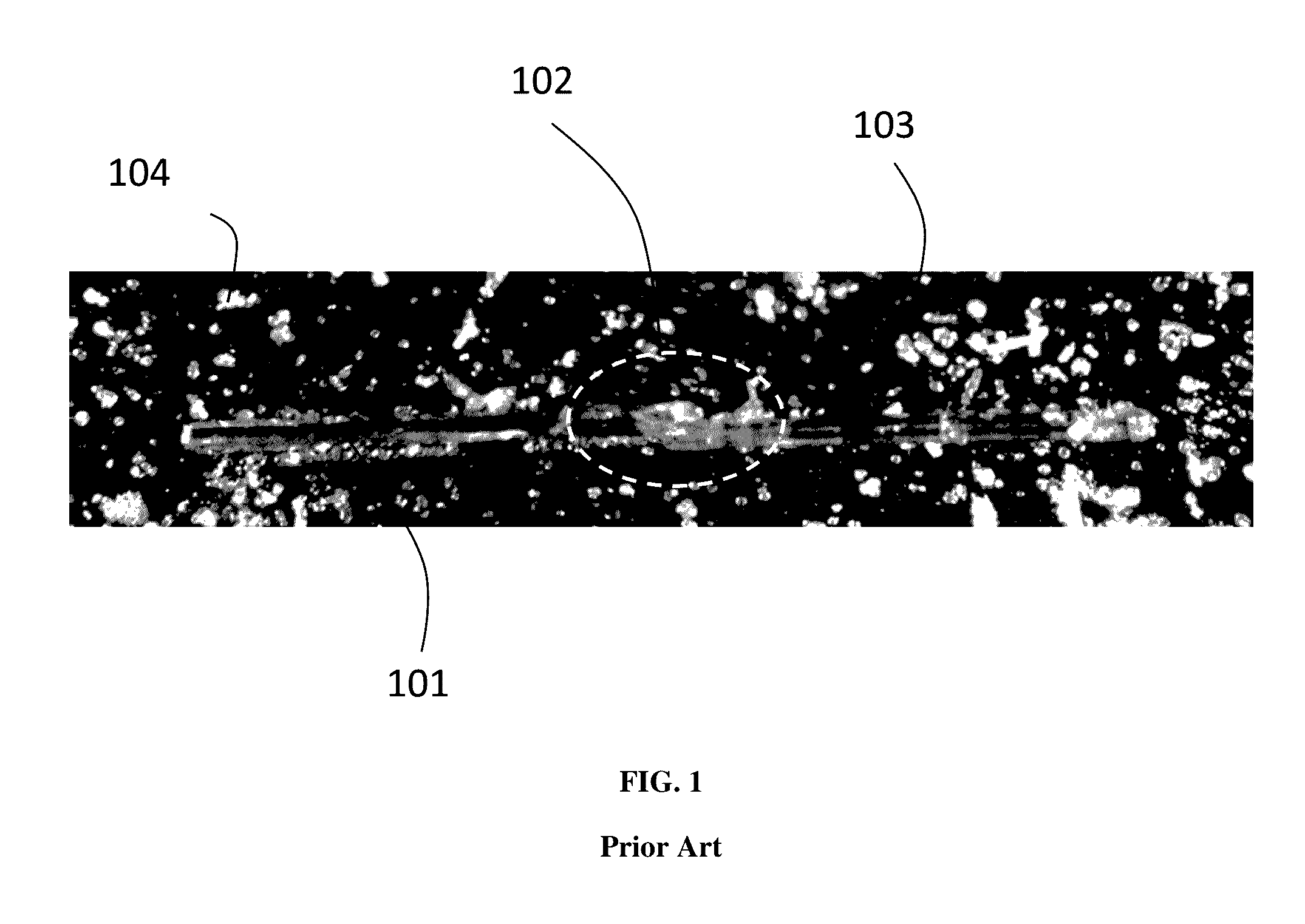
Although crystalline fibers offer a great potential for high power / energy fiber lasers as well as harsh environment fiber optic sensors, the performance of current crystalline fiber based lasers or sensors is largely compromised by a lack of a proper crystalline cladding.
Unfortunately, unlike glass fiber, crystalline fibers are not pulled from a vitreous melt and therefore cladding cannot be readily fabricated in the same way as amorphous glass fibers.
Although there has been some progress in this field, high quality crystalline cladding and crystalline core optical fibers are still underdeveloped.

Method used


Image

  • Method and apparatus for producing crystalline cladding and crystalline core optical fibers
  • Method and apparatus for producing crystalline cladding and crystalline core optical fibers
  • Method and apparatus for producing crystalline cladding and crystalline core optical fibers

Examples


Embodiment Construction

[0049]In the following detailed description, numerous specific embodiments are set forth to provide a thorough understanding of the apparatus and methods disclosed herein. However, as will be apparent to those skilled in the art, the present embodiments may be practiced without these specific details or by using alternate elements or processes. Embodiments as reported herein may also be combined with each other. In other instances, well-known processes, procedures, and / or components have not been described in detail so as not to unnecessarily obscure aspects of embodiments disclosed herein. As used herein in connection with numerical values the term “about” refers to ±10%.

[0050]I. Liquid Phase Epitaxy (LPE)

[0051]Embodiments as reported herein may provide methods and apparatus for preparing a crystalline cladding-crystalline core fiber optical system through liquid phase epitaxy (LPE). LPE is a method for growth of crystalline layers from a supersaturated liquid solution (flux) onto ...


PUM

PropertyMeasurementUnit
Fractionaaaaaaaaaa
Fractionaaaaaaaaaa
Angleaaaaaaaaaa

Abstract

We provide methods and apparatus for preparing crystalline-clad and crystalline core optical fibers with minimal or no breakage by minimizing the influence of thermal stress during a liquid phase epitaxy (LPE) process as well as the fiber with precisely controlled number of modes propagated in the crystalline cladding and crystalline core fiber via precisely controlling the diameter of crystalline fiber core with under-saturated LPE flux. The resulting crystalline cladding and crystalline core optical fibers are also reported.

Description

CROSS-REFERENCE TO RELATED APPLICATIONS[0001]This application claims priority to U.S. Provisional Application No. 62 / 282,636, filed on Aug. 6, 2015, and to U.S. Provisional Application No. 62 / 282,235, filed on Jul. 28, 2015. Both of those applications are incorporated by reference herein.FIELD OF INVENTION[0002]Embodiments related to methods and apparatus for fabricating crystalline cladding and crystalline core optical fibers. Applications of the clad crystalline fibers to fiber lasers, fiber amplifiers, fiber sensors, and other fiber optic components and devices are also reported.BACKGROUND OF THE RELATED ART[0003]The importance of crystalline optical fibers goes back at least to the introduction of laser melting technology in 1976. See, e.g., U.S. Pat. No. 3,944,640. Crystalline fibers may be, for example Neodymium (Nd) / Ytterbium (Yb) / Erbium (Er) doped yttrium aluminum garnet (YAG) fibers. In comparison to glass optical fibers, crystalline fibers offer a number of advantages. J. ...

Claims


Application Information

Patent Timeline
IPC IPC(8): G02B6/02C03C13/04C30B29/22C30B9/00C30B19/12C30B19/04G02B6/036C30B1/04
CPCG02B6/02395G02B6/03622C03C13/048C30B29/22C30B9/00C30B19/12C30B19/04C30B1/04C04B35/44C04B35/62236C04B35/62852C04B35/62897C04B35/6455C04B2235/3224C04B2235/3225C04B2235/3418C04B2235/526C04B2235/5264C04B2235/6021C04B2235/6581C04B2235/662C04B2235/764C04B2235/9653G02B6/03633H01S3/067H01S3/094007H01S3/1611H01S3/162H01S3/1623H01S3/1643
Inventor YIN, SHIZHUOLUO, FANG
Owner PENN STATE RES FOUND
Learn More